🌐 Networking Fundamentals
From the wire up: the layered models, Ethernet and the PHY, switching and ARP, IP and routing, UDP and TCP, the socket API, and the tools to see it all.
6.1 How machines talk
Programs on different machines cannot share registers, stack frames, pointers, or cache lines. They can only cause physical signals to leave one machine, cross some medium, and be interpreted by another. Networking turns that unfriendly fact into a usable abstraction: one process writes bytes, another receives bytes, and the machines in between need not understand the application.
The first problem is representation. A sender must decide where a message begins and ends, which destination it is for, what kind of payload it carries, and what to do when the world is imperfect. Bits may be corrupted. Frames may be dropped. Links have finite speed. Two transmitters may want the same medium. A receiver may be slower than the sender. A path may cross several link technologies before it reaches the destination. There is no single magic operation called "send"; there is a stack of smaller agreements.
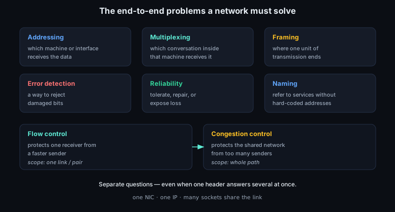
A useful way to name those agreements is to list the end-to-end problems every real network must solve. Addressing says which machine or interface should receive the data. Multiplexing says which conversation inside that machine should receive it, so many sockets can share one NIC and one IP address. Framing says where one unit of transmission ends and the next begins. Error detection gives the receiver a way to reject damaged bits. Reliability decides whether loss is tolerated, repaired, or exposed to the application. Flow control protects a receiver from a faster sender; congestion control protects the shared network from too many senders. Naming lets humans and programs refer to services without hard-coding numeric addresses. The important point is that these are separate questions, even when one protocol header carries answers to several of them.
The second problem is scope. A network interface card can put symbols on copper, fiber, or radio, but it should not need to know what a DNS query or HTTP request means. An application wants to name a peer and exchange data, but it should not need to know which line code the PHY is using. The way out is layering: each layer offers a service upward and uses a service below. The application deals in requests or streams. The transport layer deals in ports and delivery semantics. IP deals in packets that can cross networks. Ethernet deals in local frames and MAC addresses. The PHY deals in electrical or optical signaling.
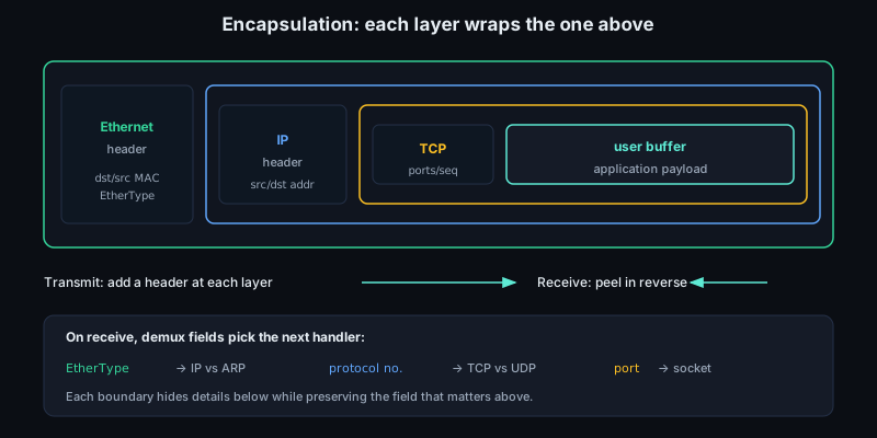
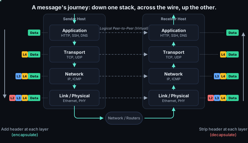
Layering works because each boundary hides most details while preserving the details that matter. The layer below wraps the layer above in its own header, a process called encapsulation. A user buffer becomes transport payload; transport adds a TCP or UDP header; IP adds source and destination addresses; Ethernet adds local delivery information; the NIC finally transmits bits. On receive, the machine peels those wrappers in the opposite direction and uses fields such as EtherType, IP protocol number, and port number to choose the next handler.
This separation is not academic tidiness; it is what lets the Internet scale. A link can change from copper Ethernet to optical Ethernet without teaching browsers a new API. A transport can add retransmission, pacing, or encryption-adjacent state without requiring every switch to participate. Some functions, such as final correctness of file transfer or end-to-end security, cannot be completely guaranteed by the middle of the network because only the endpoints know the full intent. The lower layers can reduce error rates, drop impossible frames, and provide useful hints, but the endpoints still have to decide what "correct delivery" means.
The abstraction is byte-oriented for the application, but packet-oriented almost everywhere below it. A TCP socket may accept a 64 KiB write, yet the wire will carry a sequence of frames constrained by MTU, link-layer overhead, congestion control, and the transmit queue. A UDP socket preserves message boundaries, but still has to fit those messages into IP packets and link frames. IP itself is best-effort: it can route a datagram across networks, but it does not promise delivery, ordering, uniqueness, latency, or capacity. Those promises, when they exist, are built above IP or enforced locally by queues, timers, drops, and backpressure.
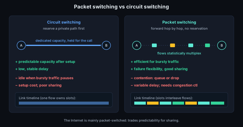
The Internet is mainly a packet-switched system. It does not reserve a private circuit with fixed capacity before two applications talk. Instead, each packet carries enough metadata to be forwarded hop by hop, and packets from many flows statistically multiplex onto the same links. That is efficient because most applications are bursty: a web client waits, sends a small request, waits again, then receives a burst of response data. The tradeoff is contention. When bursts overlap, packets wait in queues or get dropped. Circuit switching gives more predictable capacity after setup; packet switching gives better sharing and failure flexibility, at the cost of variable delay and the need for congestion control.
The boundary between "packet" and "metadata" is also important. A packet in a kernel is rarely just a flat byte array. It is usually a buffer plus facts about that buffer: protocol offsets, checksum state, VLAN tags, flow hashes, timestamps, queue mapping, and ownership rules. A descriptor in a NIC ring is the same idea at a lower level: an address, a length, flags, and status bits that let hardware and software hand ownership back and forth.
This matters for C code because wire data is hostile input. Header fields are in network byte order. Header lengths are variable. Options may be present. An IPv4 header is not always 20 bytes. A TCP header is not always 20 bytes. An Ethernet frame may have one or more VLAN tags before the payload type that the code actually wants. Robust parsers prove each length before reading the next field, avoid assuming natural alignment, and treat every offset addition as a potential overflow or bounds error.
MTU is another place where the layers meet. Ethernet commonly carries a 1500-byte IP payload, but that is not a law of networking; it is a configuration and path property. Tunnels, VLAN tags, PPPoE, jumbo frames, and virtual switches all change the amount of useful payload that fits without fragmentation or segmentation. IPv4 can fragment in the network unless prohibited, while IPv6 leaves fragmentation to endpoints. Modern stacks therefore lean heavily on path MTU discovery, TCP maximum segment size selection, and offloads that let software describe a large logical transfer while hardware emits many legal frames.
Offload does not remove protocol work; it moves the point where the work becomes concrete. With checksum offload, memory may contain a partial checksum state while the wire contains the final checksum. With TCP segmentation offload, the kernel may queue one large TCP buffer while the NIC transmits many Ethernet frames. With generic receive offload or large receive offload, the receive path may merge several wire packets into one larger object before the transport consumes it. This is useful for throughput, but it makes debugging depend on the observation point.
Queues are the hidden machinery behind most network behavior. There are application socket buffers, transport retransmission queues, qdiscs, driver queues, NIC rings, switch queues, and receiver backlog queues. A packet can be delayed or dropped at any of them. Flow control is also layered: Ethernet pause frames, TCP receive windows, congestion control, socket buffer limits, and application read rates solve different problems at different scopes. When throughput collapses or latency spikes, the useful question is often not "is the network slow?" but "which queue is growing, who owns it, and what signal is supposed to drain it?"
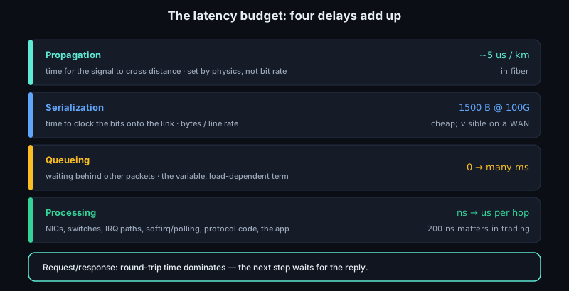
Latency has a budget. Propagation delay is the time for the signal to cross distance; in fiber it is roughly 5 us per kilometer because light in glass is slower than light in vacuum. Serialization delay is the time to clock the bits onto the link: a 1500 byte payload is cheap on 100 Gbit/s Ethernet and visible on a slow WAN link. Queueing delay is waiting behind other packets. Processing delay is the time spent in NICs, switches, interrupt paths, softirq or polling loops, protocol code, and the application. For many request/response protocols, round-trip time dominates because the next step cannot begin until a reply or acknowledgment comes back. Cutting 200 ns from a driver path matters in trading or storage fabrics; cutting one avoidable RTT matters almost everywhere.
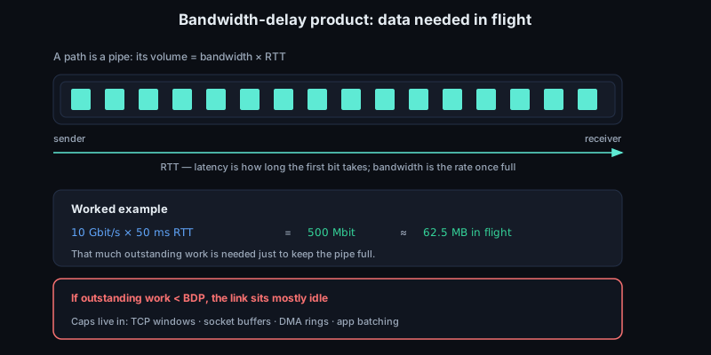
Bandwidth and latency are different axes. Bandwidth is how fast bits can be delivered once the pipe is full. Latency is how long the first useful bit takes to arrive. The bandwidth-delay product is the amount of data needed in flight to fill the path: bandwidth * RTT. A 10 Gbit/s path with 50 ms RTT has about 500 Mbit, or 62.5 MB, of data in flight at full rate. If TCP windows, socket buffers, DMA rings, or application batching cannot sustain that much outstanding work, the link can be mostly idle even though every individual component is "fast".
This is why NIC and driver work has a precise shape. A driver mostly handles the lower boundary: DMA buffers, descriptor rings, checksum offload metadata, receive-side steering, timestamps, interrupts, and link state. It must preserve enough protocol information for the kernel stack while moving packets without unnecessary copies. If you understand each layer's promise, you can tell whether a bug belongs in PHY negotiation, MAC filtering, ARP resolution, routing, transport state, or application logic.
When you load a web page, all of these ideas appear in a few milliseconds or seconds. The browser starts with a name, asks DNS for addresses, chooses a local socket, and relies on routing to find a next hop. The host may need ARP or neighbor discovery to learn a local MAC address. TCP or QUIC establishes transport state, TLS establishes security state, and HTTP names the object inside the server. The NIC and driver turn buffers into descriptors, descriptors into DMA, DMA into frames, and frames into symbols. The response comes back as packets that may be reordered, coalesced, checksummed by hardware, steered to a receive queue, copied or mapped into kernel buffers, and finally delivered to the application. Later sections unpack each step; for now, the useful habit is to see one page load as a chain of scoped promises rather than one opaque network operation.
The same model helps when reading packet traces. A local Ethernet destination MAC only identifies the next hop on that link, not necessarily the final IP destination. A TCP port identifies a transport endpoint, not a process in every namespace or after every NAT. A checksum failure may be a real corruption event, an offload artifact, or a capture made before hardware filled the field. A retransmission may indicate loss, but it may also follow reordering, delayed acknowledgments, timer granularity, or receiver behavior. Low-level networking work is mostly the discipline of keeping these scopes separate while following one packet, buffer, or descriptor through the machine.
Sources
- RFC 1122: Requirements for Internet Hosts - Communication Layers
- RFC 791: Internet Protocol
- RFC 8200: Internet Protocol, Version 6 Specification
- IEEE 802.3 Ethernet Working Group
- RFC 1958: Architectural Principles of the Internet
- RFC 6349: Framework for TCP Throughput Testing
- RFC 896: Congestion Control in IP/TCP Internetworks
6.2 Layered models and encapsulation
Layering gives each part of communication a narrow job. A program should not know how an electrical signal is encoded on copper. A router should not understand an HTTP body. A NIC should not parse a database protocol to transmit bytes. Each layer adds information for its own peer, then hands the result below.
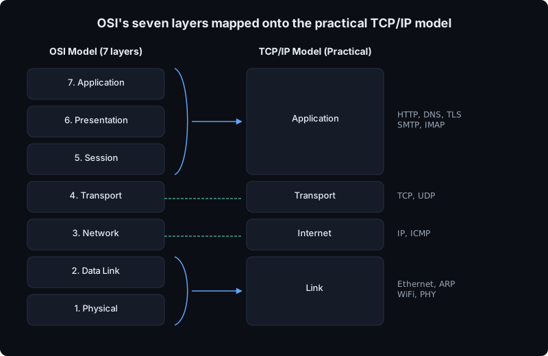
The OSI model is the traditional vocabulary. ISO/IEC 7498-1 defines it as a reference model, not as the implementation plan used by most operating systems. Its seven layers are physical, data link, network, transport, session, presentation, and application. The lower four are the ones you meet in packet traces and driver work. The physical layer owns signaling: voltages, light, modulation, clock recovery, link training. The data link layer owns local delivery: Ethernet framing, MAC addresses, frame check sequence, VLAN tags, and media access rules. The network layer owns delivery across links: IP addressing, routing, IPv4 fragmentation, hop limits, and next-hop selection. The transport layer owns end-to-end process communication: UDP ports and datagrams, or TCP byte streams, sequence numbers, acknowledgments, retransmission, and flow control. The upper OSI layers are real concepts, but in normal Internet software they are not stable kernel boundaries. A TLS record parser, an ASN.1 decoder, a JSON library, and an RPC request dispatcher may all sit in one process above a TCP socket.
The TCP/IP model matches the Internet stack more directly. RFC 1122 describes host software in terms of link layer, Internet layer, transport layer, and application layer. It does not usually split OSI session and presentation into separate layers; TLS, DNS message encoding, HTTP framing, RPC stubs, and serialization live above transport as needed. Engineers still say "Layer 2" for Ethernet, "Layer 3" for IP, and "Layer 4" for TCP or UDP, while debugging TCP/IP rather than pure OSI. This shorthand is useful as long as it is treated as a map, not a law of nature. The Linux network stack has link devices, IP input and output paths, transport protocol handlers, sockets, qdiscs, netfilter hooks, tunneling devices, namespaces, and BPF programs. Those pieces often correspond to layers, but they are not a neat seven-object pipeline.
The key idea is ownership. Ethernet owns MAC addresses because they are meaningful only on the current LAN segment. IP owns source and destination IP addresses because those remain the logical endpoints as the packet crosses routers. TCP and UDP own ports because ports select sockets inside hosts, not machines on a wire. An application owns its own message boundaries and semantics.
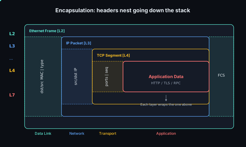
Encapsulation is how ownership appears in memory and on the wire. Suppose an application writes bytes to a TCP socket. TCP treats them as payload, chooses sequence numbers, and prepends a TCP header. IP treats the TCP segment as payload, prepends an IP header, and sets the IP protocol field to identify TCP. Ethernet treats the IP datagram as payload, prepends an Ethernet header, and appends the frame check sequence on the wire. Conceptually the nesting is:
- Ethernet header
- IP header
- TCP or UDP header
- application bytes
- Ethernet FCS
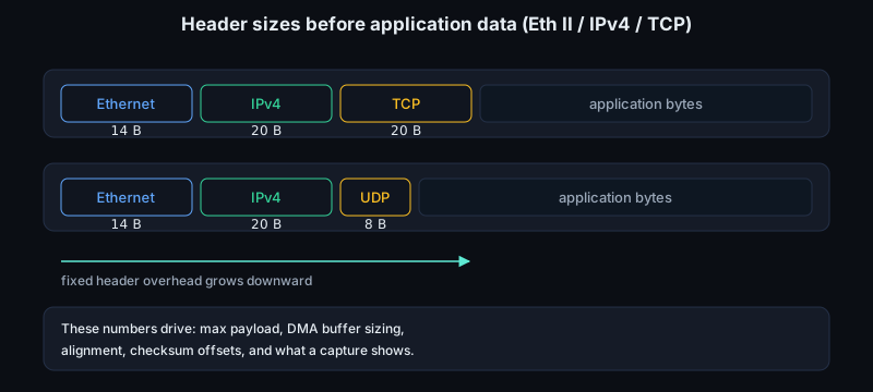
For a common Ethernet II, IPv4, TCP packet with no options or VLAN tag, the normal header sizes before application data are 14 bytes of Ethernet, 20 bytes of IPv4, and 20 bytes of TCP. UDP uses an 8 byte header. Those numbers affect maximum payload, DMA buffer sizing, alignment, checksum offsets, and what a capture tool displays when hardware offload has deferred work until transmit.
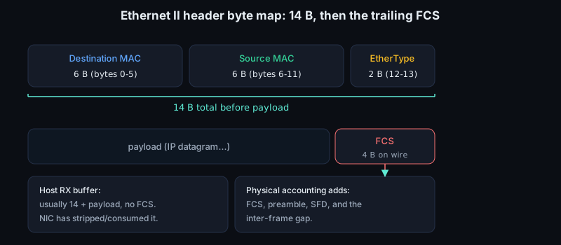
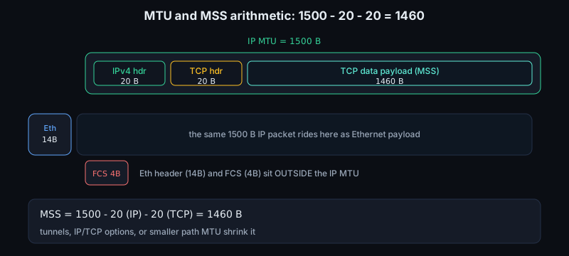
The Ethernet number deserves to be read precisely. The Ethernet II header is 6 bytes of destination MAC, 6 bytes of source MAC, and 2 bytes of EtherType: 14 bytes total before the payload. The 4 byte FCS is part of the frame on the wire, but most host receive paths do not include it in the packet buffer delivered to software. A driver author still cares about it because the descriptor may report FCS, length, CRC, or alignment errors; a packet parser usually does not advance through it because the NIC has already consumed or stripped it. That distinction explains why capture tools often show an Ethernet frame as 14 + payload while physical-layer accounting includes the trailing FCS, preamble, start-frame delimiter, and inter-frame gap.
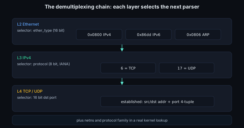
Encapsulation also means each layer needs an explicit demultiplexing field for the next parser. Ethernet II uses ether_type: 0x0800 for IPv4, 0x86dd for IPv6, 0x0806 for ARP. VLAN tagging inserts another header and moves the useful EtherType after the tag control information. IPv4 uses the protocol byte; IPv6 uses next_header, possibly after extension headers. TCP and UDP use the destination port, but a real socket lookup usually keys on more than that. A connected TCP socket is identified by the 4-tuple of source address, source port, destination address, and destination port, plus the network namespace and protocol family in an operating system implementation. UDP lookup has connected, bound, wildcard, multicast, and reuse cases. The simple diagram says "port selects process"; the kernel code has to handle all the ambiguous cases.
The demultiplexing chain is therefore concrete, not philosophical. At Layer 2, the Ethernet Type field chooses the next parser: IP, ARP, IPv6, or another link payload. At Layer 3, the IPv4 Protocol field is an 8 bit selector; IANA assigns 6 to TCP and 17 to UDP. At Layer 4, TCP and UDP both begin with 16 bit source and destination ports. For a TCP listener, the destination port gets a SYN to the right service; for an established TCP connection, the full 4-tuple distinguishes many simultaneous connections to the same port. For UDP, the destination port is often enough for a simple server, but connected UDP sockets, wildcard binds, multicast delivery, and SO_REUSEPORT make the implementation rules more subtle than the packet format.
The MTU and MSS arithmetic is another place where layers meet in a very practical way. Ethernet's common payload MTU is 1500 bytes, meaning the IPv4 packet must fit inside 1500 bytes of Ethernet payload. With no IP options and no TCP options, IPv4 consumes 20 bytes and TCP consumes 20 bytes, so the largest TCP data payload is 1500 - 20 - 20 = 1460 bytes. That 1460 byte value is the familiar IPv4 TCP MSS on an ordinary Ethernet path. It is not "Ethernet payload minus Ethernet header"; the 14 byte Ethernet header and 4 byte FCS live outside the IP MTU. Add a tunnel, IP options, TCP options, or a smaller path MTU and the available MSS shrinks. A low-level bug here can create fragmentation, black-holed packets when PMTUD fails, or TSO packets that the NIC cannot legally segment.
Decapsulation is the reverse path, but it is not just "strip a header." Each layer validates and interprets its own control information before handing up the payload. The Ethernet receive path checks whether the frame is for the NIC, a multicast group, broadcast, or promiscuous mode; hardware normally verifies the FCS before the host sees the frame. The Ethernet type says whether the payload is IPv4, IPv6, ARP, or something else. IP checks version, header length, total length, IPv4 header checksum, destination address, TTL or hop limit, and protocol number. TCP or UDP checks ports and checksum state, then finds a socket or reports that none exists. A robust parser also checks that each advertised header length fits inside the received buffer before advancing a pointer. An IPv4 header length smaller than 20, a TCP data offset smaller than 20, a total length beyond the DMA buffer, or a truncated VLAN header is not a higher-layer problem. It is malformed input at the layer that claimed those bytes existed.
In C, this usually reduces to careful bounds checks before every cast or load. The code below is only the first step of a real parser, but it shows the shape of the discipline: compute the next offset from the current header, validate it against the received length, then decide which parser owns the next bytes.
if (len < 14)
    return DROP;
eth_type = load_be16(buf + 12);
off = 14;
if (eth_type == 0x8100) {
    if (len < off + 4)
        return DROP;
    eth_type = load_be16(buf + off + 2);
    off += 4;
}
On receive, the implementation therefore walks through bytes and metadata together. A NIC DMA engine places frame data into host memory and reports descriptors with length, checksum status, VLAN status, hash values, timestamp state, and error bits. The driver builds an sk_buff or page-backed fragment list, sets protocol metadata, and hands the packet to the stack through the device receive path. The stack may pull enough linear data to inspect the MAC header, then the network header, then the transport header. It may drop early, redirect through XDP or TC/BPF, pass through bridge or VLAN handling, defragment IP before transport lookup, or deliver a clone to packet capture. The layer model still describes what the bytes mean; the receive path describes who is allowed to look at them and when.
A router gives a good test of the model. It receives an Ethernet frame, removes the local Ethernet wrapper, makes a Layer 3 forwarding decision using the IP destination address, decrements the TTL or hop limit, and emits a new Ethernet frame for the next link. The IP packet is not delivered "inside the same Ethernet frame" across the Internet. Every hop uses a fresh link-layer envelope.
For NIC and driver work, the abstraction is useful but never absolute. A modern NIC may classify packets by inspecting Ethernet, IP, and TCP or UDP headers for receive-side scaling. It may compute checksums, segment a large TCP buffer, coalesce received segments, strip VLAN tags, timestamp packets, or steer flows to queues. Linux represents packets with struct sk_buff, whose metadata records where the MAC, network, and transport headers begin. The driver and stack therefore share a precise contract: the bytes are layered, but hardware may operate on several layer boundaries at once.
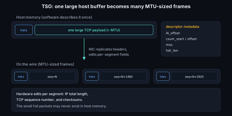
Layering leaks most obviously around performance features. TCP segmentation offload lets the kernel hand the NIC a large TCP payload and a set of header templates; the small on-the-wire packets may never exist as separate full packets in host memory before transmit. Large receive offload and generic receive offload can merge several wire packets into a larger buffer before TCP sees them. Checksum offload means a packet capture taken above the driver may show a checksum that looks wrong because hardware has not filled it in yet, or because the stack recorded that it was already verified. RSS hashes are nominally a receive-queue feature, but they depend on Layer 3 and Layer 4 fields. A firewall rule may match an application port while running in a hook that sits before local socket delivery. These are not violations of the model; they are engineering shortcuts that preserve the externally visible protocol while moving work to cheaper places.
Transmit offload makes the boundary especially explicit in driver code. For TSO or GSO, software may describe one large buffer with metadata such as transport-header offset, checksum start, checksum offset, MSS, and total header length. The NIC then replicates the Ethernet, IP, and TCP headers, edits per-segment fields such as IP total length, TCP sequence number, and checksums, and emits MTU-sized frames. VLAN insertion is similar: the host buffer may contain an untagged Ethernet header while the descriptor tells hardware to insert a 4 byte 802.1Q tag between source MAC and EtherType. The layer model is still true on the wire, but the memory image, descriptor metadata, and captured packet may each show a different stage of construction. That is why kernel-bypass code, DPDK poll loops, and ordinary kernel drivers all carry explicit header offsets instead of relying on "the TCP header is always at byte 34."
Tunnels and overlays add another leak. VXLAN, GRE, IPsec, WireGuard, and similar mechanisms put one packet inside another packet. After encapsulation, an inner Ethernet or IP header becomes payload for an outer UDP or IP header. A NIC or kernel fast path may need to parse outer headers for delivery to the tunnel endpoint and inner headers for checksum, segmentation, filtering, or flow steering. That is why driver feature flags distinguish ordinary checksum offload from tunnel-aware offload, and why packet analyzers display nested protocol stacks rather than one flat layer number.
This is why "which layer?" is not pedantic. It tells you which identifier is stable across which scope, which checksum covers which bytes, which device may rewrite which header, and where a bug can live. A bad MAC address is a local-link problem. A wrong route is an IP problem. A mismatched port is transport demultiplexing. A malformed message after a valid TCP receive is an application problem. Encapsulation gives you a map from raw bytes to responsibility.
Sources
- RFC 1122: Requirements for Internet Hosts - Communication Layers
- RFC 791: Internet Protocol
- ISO/IEC 7498-1:1994 OSI Basic Reference Model
- Linux kernel documentation: struct sk_buff
- RFC 894: IP Datagrams over Ethernet
- IANA Assigned Internet Protocol Numbers
- Linux kernel documentation: Segmentation Offloads
6.3 Ethernet, MAC, and the PHY
Ethernet is the local delivery system underneath most IP networks. IP talks about moving packets between networks, but on a LAN the immediate act is simpler: put a frame onto a physical link so the next directly attached device can receive it.
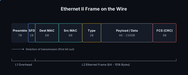
An Ethernet transmission begins before the frame proper. The transmitter sends a 7 byte preamble, traditionally the repeating pattern 0x55, followed by a 1 byte start frame delimiter, 0xD5. These bytes are not delivered as packet data to software. They give the receiver enough alternating signal transitions to lock onto bit timing and then mark exactly where the MAC frame begins. In a packet capture you usually see the destination MAC address first, not the preamble.
The normal Ethernet II MAC frame then has a small fixed header, a variable payload, and a trailer. The destination MAC address is 6 bytes, followed by the source MAC address, also 6 bytes. The next 2 bytes are normally an EtherType: 0x0800 for IPv4, 0x0806 for ARP, 0x86DD for IPv6. In IEEE 802.3 framing, values up to 1500 represent a length instead; EtherType values start at 0x0600, which leaves the two interpretations unambiguous. A VLAN tag, when present, inserts 4 bytes after the source address, with EtherType 0x8100 introducing the tag and another type or length field after it.
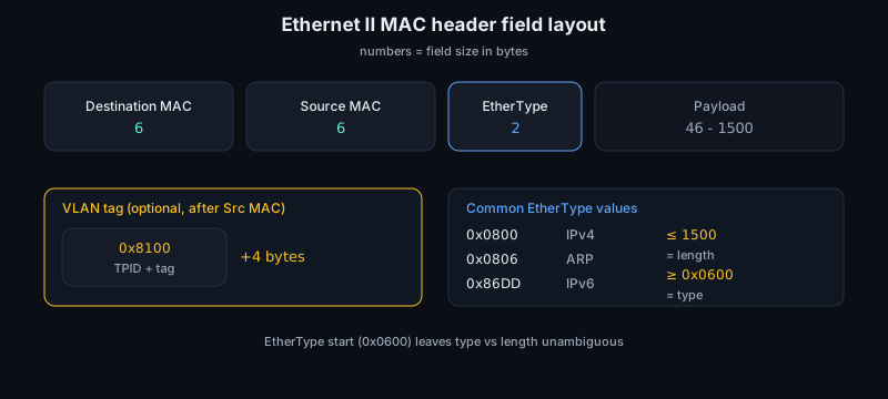
The payload is at least 46 bytes and at most 1500 bytes for the traditional Ethernet MTU. If the higher layer supplies less than the minimum, the MAC pads the frame so that the frame from destination address through frame check sequence is at least 64 bytes. That minimum comes from classic shared-medium Ethernet collision detection, but it remains part of the format even on modern full-duplex switched links. Many NICs and switches also support jumbo frames, but those are a configured extension, not the baseline assumption.
Jumbo frames usually mean an MTU around 9000 bytes, but there is no single universal jumbo-frame size in Ethernet itself. Every hop in the L2 path must agree, including NIC, switch port, virtual switch, and any tunnel endpoint that adds outer headers. For driver work, "supports jumbo" is therefore not one bit: the receive buffers, scatter-gather limits, maximum descriptor length, VLAN tag handling, headroom, and XDP or kernel-bypass buffer layout all have to match the largest frame the hardware may DMA.
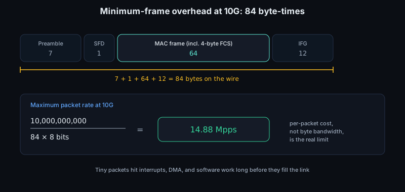
The minimum-size case is where Ethernet overhead becomes visible. A 64 byte MAC frame already includes the 4 byte FCS, but the wire also carries the 7 byte preamble, 1 byte start frame delimiter, and 12 byte interframe gap. That is 84 byte times per minimum packet on the medium. At 10G, the maximum packet rate for back-to-back minimum frames is therefore 10,000,000,000 / (84 * 8), or about 14.88 million packets per second. This is why "10 gigabits" does not mean a host can receive arbitrary tiny packets cheaply: interrupt moderation, descriptor cache misses, DMA writes, RSS distribution, and per-packet software work hit before byte bandwidth does.
The last 4 bytes are the frame check sequence, a CRC-32 computed by the MAC over the frame fields from destination address through payload and padding. The FCS is detection, not repair. A bad FCS means the receiver should drop the frame, and most NICs do that in hardware before DMA. This matters when debugging receive paths: if software sees a packet, the NIC has usually already accepted the FCS unless a special capture or error-reporting mode is enabled.
The FCS is also a common source of confusion in tooling. A normal AF_PACKET capture, pcap trace, or kernel receive path usually starts at the destination MAC address and ends at the last payload byte; preamble, start delimiter, inter-frame gap, and FCS are gone. Some NICs can be configured to retain the FCS in the DMA buffer, and some expose frames with bad CRC through a diagnostic path, but that is not the default contract. A driver therefore must know whether hardware has stripped 4 bytes, appended them, or reported them only through descriptor status. Getting this wrong creates off-by-four length bugs that look like truncated packets, bogus trailing bytes, or checksum failures in higher layers.
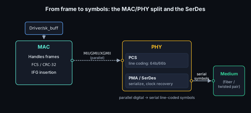
The MAC and the PHY split the job at a useful boundary. The MAC understands frames: addresses, padding, FCS generation and checking, inter-frame gap, flow-control frames, counters, filters, queues, DMA descriptors, and often checksum or segmentation offloads. The PHY understands the link: signaling, auto-negotiation, link training, clock recovery, equalization, error counters, and the electrical or optical rules for a particular Ethernet variant. In a Linux driver this split often appears as one driver for the Ethernet controller and another for the PHY, connected through MDIO-managed registers or a phylink-style interface.
The boundary is logical, not always a chip boundary. A server NIC may integrate several MACs, PCS blocks, SerDes lanes, and management processors behind one PCIe function. An embedded SoC may have the MAC on-chip and an external copper PHY on an MDIO bus. A switch ASIC may terminate many PHY-facing ports and present frames internally to forwarding logic instead of to host memory. In all cases the software-facing receive object is not exactly "what was on the wire"; it is a DMA buffer plus metadata produced by hardware after classification, validation, timestamping, VLAN handling, and sometimes packet steering.
Between MAC and PHY is a media-independent interface family: MII, GMII, RGMII, SGMII, XGMII, XLGMII, and others. "Independent" does not mean identical; it means the MAC can hand frame bytes or control symbols across a defined interface without knowing whether the far side is twisted pair, backplane traces, direct-attach copper, or fiber. At 10G and above this interface is often wide and clocked in parallel inside the chip, then converted near the pins into high-speed serial lanes.
The names tell you roughly where you are in the design. MII was the classic 10/100 interface. GMII presents gigabit Ethernet as an 8 bit data path with separate transmit and receive clocks, while RGMII reduces pin count by transferring data on both clock edges. XGMII is the 10G MAC-side interface, logically 32 data bits plus control per direction at 156.25 MHz. SFI is not a MAC byte bus in the same sense; it is a high-speed serial electrical interface toward an optical module, direct-attach cable, or retimer. When a driver exposes link modes, module types, and PHY interface modes, these names are the vocabulary connecting board wiring to software configuration.
IEEE 802.3 also splits the PHY internally. The PCS is the physical coding sublayer: it turns MAC-side data and control characters into coded blocks, inserts idles, recognizes start and terminate markers, performs block alignment, and reports local or remote faults. The PMA is the physical medium attachment: serialization, deserialization, clock recovery, lane distribution, and electrical attachment to the PMD below it. For debugging, "PCS block lock lost" is a different class of failure from "MAC ring full" or "optical receive power low"; the frame may never have reached the MAC as a candidate packet.
That conversion is the job of SerDes: serializer/deserializer logic. A SerDes takes parallel data from the digital side, encodes it for the channel, drives one or more lanes, and recovers data and clock at the receiver. Line coding exists because raw frame bits are not a good physical signal. The receiver needs transitions for timing, structure for block alignment, and control symbols for idle, start, terminate, and error conditions. Older gigabit-style serial Ethernet variants use 8b/10b coding, which maps 8 data bits into 10 transmitted bits at a cost of 25% overhead. 10GBASE-R uses 64b/66b, adding a 2 bit sync header to 64 bits of scrambled data or control information, reducing coding overhead to 3.125%.
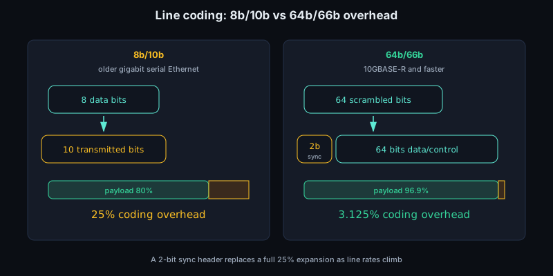
The line-rate math follows directly from that coding. A 1000BASE-X lane carrying 1 Gb/s of MAC data uses 8b/10b, so it transmits 1.25 Gbaud of coded symbols. 10GBASE-R carries 10 Gb/s at the MAC service interface but sends 66 bits for every 64 bits after PCS encoding, so the serial rate is 10 * 66 / 64 = 10.3125 Gb/s, often described casually as about 10.3125 GBd on a single NRZ lane. The same 64b/66b overhead appears in many faster Ethernet families before other features, such as lane striping or FEC, add their own details. 25G single-lane Ethernet is not "two and a half times 10GBASE-R" at the pin; modern 25G PHYs have their own lane rates, FEC choices, and module/backplane rules.
The physical link is therefore not just "a cable." A 1000BASE-T copper PHY uses all four twisted pairs with echo cancellation and digital signal processing. A 10GBASE-SR optical PHY uses short-reach multimode fiber. Backplane Ethernet must survive loss, reflection, crosstalk, and connector discontinuities. Modern high-speed links may use multiple lanes, PAM4 signaling, forward error correction, and link training. The MAC frame abstraction survives across all of these.
Auto-negotiation and link training are separate but related state machines. Auto-negotiation decides a mutually supported mode: speed, duplex, pause capability, sometimes FEC, and sometimes lane count or reach. Link training then tunes the physical channel so that the chosen mode can run with enough margin. On copper and backplane links this can include transmit equalizer coefficients, receiver adaptation, polarity correction, lane ordering, and lock to block markers. A driver that reports Link detected: yes too early can hand the stack a carrier-up interface while the PCS is still losing alignment or while FEC is accumulating uncorrectable blocks.
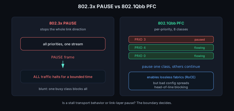
Pause negotiation is part of this story because it changes loss behavior under congestion. IEEE 802.3x PAUSE is a link-level MAC control mechanism: a receiver can ask its peer to stop transmitting for a bounded time, but classic PAUSE stops the whole link direction. IEEE 802.1Qbb Priority-based Flow Control narrows that to traffic classes, so one priority can be paused while others continue. This is the bridge from ordinary Ethernet into "lossless" data-center fabrics used by RoCE: the NIC and switch cooperate to avoid drops for selected priorities. It is powerful and dangerous. A bad PFC configuration can spread head-of-line blocking, so low-level engineers need to know whether packet loss, latency spikes, or zero-window-looking stalls are coming from transport behavior or from link-layer pause.
Counters are the best way to place a fault on the right side of the boundary. MAC counters describe frames accepted, filtered, dropped, undersized, oversized, paused, errored, or missed because rings ran out. PHY and PCS counters describe symbol errors, block lock loss, FEC corrected and uncorrected codewords, lane faults, remote faults, and link transitions. The distinction matters. A growing RX missed counter with no PHY errors usually means software or DMA could not keep up. Growing FCS or alignment errors point toward the receive MAC, PCS, or physical channel. Growing FEC corrected counters may be acceptable on a high-speed link; growing uncorrected counters are packet loss.
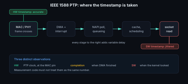
IEEE 1588 Precision Time Protocol adds another reason the MAC boundary matters. For accurate packet timing, the timestamp should be taken in hardware close to the point where the frame crosses the MAC, not later in the kernel after DMA completion, interrupt moderation, NAPI polling, queueing, and cache effects. On transmit, the useful time is when the packet actually leaves the MAC or PHY-facing pipeline, not when software filled a descriptor. On receive, it is when the start or selected reference point of the frame arrived at hardware, not when a socket read returned. That is why NICs expose PTP hardware clocks and timestamp descriptor metadata, and why measurement code must treat hardware timestamps, software timestamps, and completion timestamps as different observations.
Transmit offloads complicate what a driver hands to hardware. With checksum offload, the kernel may place a pseudo-header checksum in the packet and ask the NIC to finish the L4 checksum after DMA. With TCP segmentation offload, the buffer may be much larger than the Ethernet MTU; the NIC emits many legal frames, each with its own Ethernet header, IP length, TCP sequence range, checksum, padding if needed, and FCS. With VLAN insertion, the descriptor may contain the tag while the DMA buffer does not. A capture taken before the driver, inside the host stack, after the NIC, or on an external tap can therefore show different byte streams while all of them are valid observations at different boundaries.
For NIC and driver work, this boundary explains many failure modes. If ethtool says the link is down, the problem is usually in PHY negotiation, module presence, lane training, firmware, or the peer, not in socket code. If link is up but packets do not arrive, the next questions are MAC filters, VLAN stripping, descriptor rings, DMA mapping, interrupt moderation, and receive-side scaling. Ethernet's simplicity at the frame level is deliberate: analog and coding work is pushed below the MAC, while software mostly handles buffers, queues, metadata, and policy.
Typical driver failures look mundane at the source line but precise on the wire. A receive path can recycle a page before all fragments are consumed, forget to sync a DMA mapping for the CPU, advertise a buffer length smaller than the maximum frame plus headroom, or accept a descriptor whose error bits should have caused a drop. A transmit path can ring the doorbell before descriptors are visible to the device, free an skb before completion, mishandle a linearization fallback, or assume an offload feature remains enabled after a reset. After any reset or firmware recovery, the driver must rebuild more than the PCI registers: MAC address filters, multicast tables, VLAN filters, RSS keys, queue enables, interrupt moderation, timestamping state, pause settings, and the MAC-to-PHY link mode all have to be coherent again.
Sources
6.4 Switching, ARP, and the LAN
Ethernet gives each interface a local name, the MAC address, but it does not by itself say which cable or port leads to that address. A switch supplies that missing piece. It is a bridge with multiple ports and a table, often called the forwarding database or MAC table, mapping destination MAC addresses to output ports. The key point is that this table is learned from traffic, not normally configured by hand.
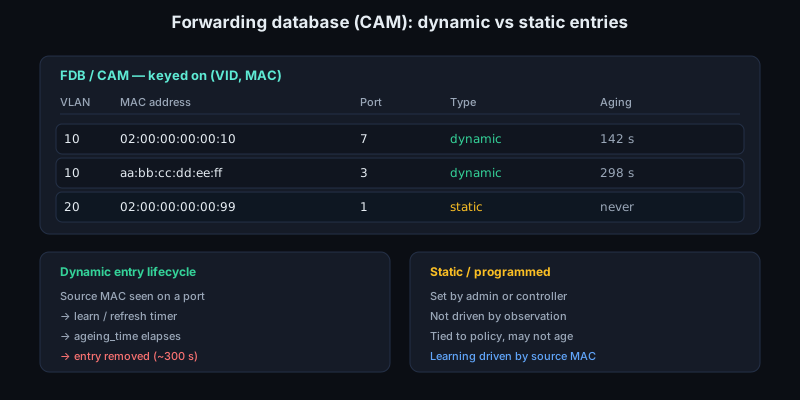
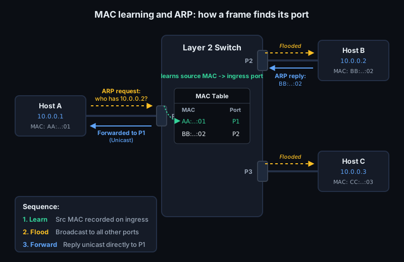
When a frame arrives, the switch first looks at the source MAC address and the ingress port. If it sees source 02:00:00:00:00:10 on port 7, it records that MAC as reachable through port 7, usually with an aging timer so stale entries disappear after movement or failure. The learned key is not only the MAC address. On a VLAN-aware bridge it is effectively (VLAN, MAC) -> port. Then it looks at the destination MAC address. If the destination is known, the switch sends the frame only toward the learned port. If the destination is unknown, or if the destination is broadcast or a relevant multicast address, the switch floods the frame out the other ports in the same LAN. This is why a quiet host may initially receive a flooded unicast frame, but later traffic to that host becomes point-to-point at layer 2.
In hardware, the forwarding database is often implemented as a content-addressable memory, or CAM, because the data plane needs to answer "which egress port matches this (VID, destination MAC)?" at line rate. Learning is driven by the source MAC, not by ARP, IP, or TCP. A switch can learn from any valid Ethernet frame, including an ARP request, an IPv4 packet, or a proprietary control frame. A dynamic FDB entry is refreshed when a frame from that source is seen and is removed when its aging timer expires. The IEEE bridge default is commonly described around 300 seconds, while Linux bridge exposes a configurable ageing_time. Static entries, port-security entries, and controller-programmed entries are different: they may not age, or they may be tied to policy rather than observation. For driver and kernel-bypass work, this distinction matters because a synthetic source MAC in a test generator or VM can poison the switch's idea of where a host lives.
This behavior is simple, fast, and local. The switch is not decrementing an IP TTL, choosing an IP next hop, or rewriting the layer-3 destination. It is forwarding an Ethernet frame within one layer-2 network. Modern switches implement the lookup in hardware tables, but the abstract operation is the same: learn from source, forward by destination, flood when necessary. The table has finite capacity, so excessive churn, virtual-machine movement, duplicate MAC addresses, or deliberate MAC flooding can turn expected unicast into unknown-unicast flooding. A saturated or unstable table often looks like intermittent packet loss, surprising captures on unrelated ports, or flows that work only after traffic has been generated in the reverse direction. Loops can amplify frames indefinitely, so bridged networks need loop prevention or a controlled topology.
A broadcast domain is the set of interfaces that receive a layer-2 broadcast frame. The Ethernet broadcast address is ff:ff:ff:ff:ff:ff. ARP requests, DHCP discovery, and some neighbor or control traffic rely on broadcast or multicast, so the size of a broadcast domain is a real scaling and failure boundary. Too large, and every host and NIC must spend work receiving and discarding traffic that is not useful to it. Too small or wrongly segmented, and hosts that expect to discover each other on the local link will not.
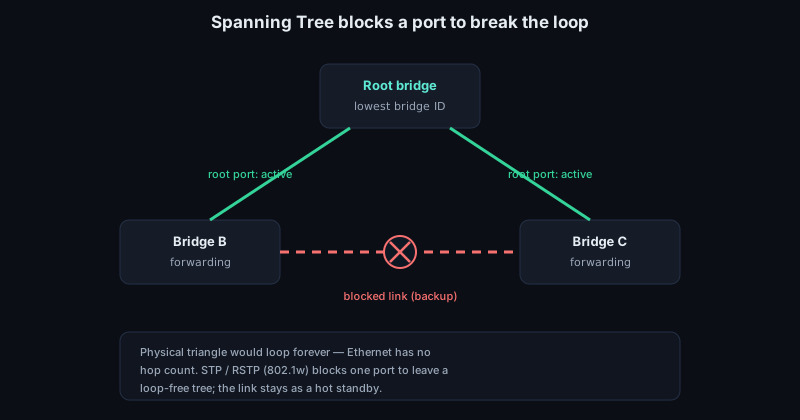
The loop problem is more severe than "a packet goes around twice." Ethernet has no hop count, so a single broadcast can circulate until links saturate. Because switches keep learning source MACs, the same source can appear to move between ports on every lap of the loop, causing MAC flapping and widespread flooding. Spanning Tree Protocol exists to compute a loop-free active topology across bridges by blocking selected ports while leaving backup physical links available. Rapid Spanning Tree, standardized as 802.1w and later folded into the bridge standards, keeps the same goal but converges faster after link changes. In a low-latency environment, STP is often treated as a guardrail rather than a normal traffic-engineering mechanism; accidental L2 loops still produce symptoms that look like random receive drops, interrupt storms, and driver instability.
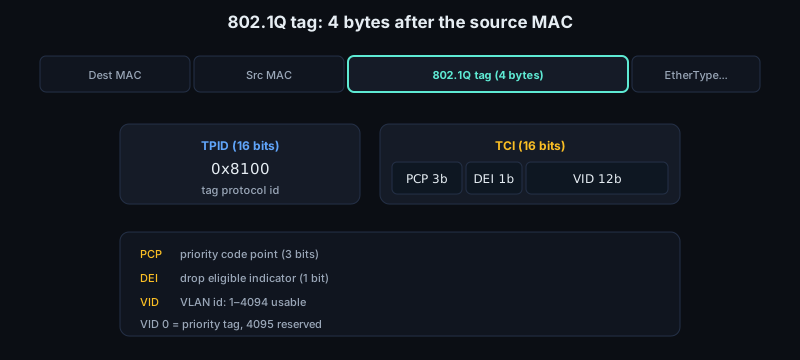
VLANs make multiple logical LANs share the same physical switching infrastructure. IEEE 802.1Q inserts a 4 byte tag after the source MAC address. The first 16 bits are the tag protocol identifier, normally TPID 0x8100, which occupies the position where an untagged frame would have had its EtherType. The next 16 bits are tag control information: 3 bits of priority code point, 1 drop eligible indicator bit, and a 12 bit VLAN identifier. VID 0 is a priority tag with no VLAN membership, and 4095 is reserved, leaving 1 through 4094 as usable VLAN IDs in the ordinary case. A switch learns MAC addresses per VLAN, not globally. MAC aa:bb:cc:dd:ee:ff in VLAN 10 is distinct from the same MAC in VLAN 20, and flooding stays inside the VLAN. Access ports usually present untagged frames to an end host and internally classify them into one VLAN. Trunk ports carry tagged frames for multiple VLANs between switches, servers, hypervisors, or VLAN-aware NICs. This scoping matters during debugging: a host can have the right IP address and still never see the ARP request if the switch port is in the wrong VLAN, the trunk does not allow that VLAN, the native VLAN expectation differs at the two ends, or the NIC driver strips a tag that the capture point was expected to show.
ARP connects the IP model to this Ethernet model. IPv4 wants to send to an IP next hop on the local link, but Ethernet needs a destination MAC address. If host A, 192.0.2.10/24, wants to send to 192.0.2.20, it decides the destination is on-link. Without a neighbor-cache entry, it sends an ARP request in an Ethernet broadcast frame with EtherType 0x0806: "Who has 192.0.2.20? Tell 192.0.2.10." Every host in that broadcast domain receives the request, but only the owner should reply, normally with a unicast ARP reply containing its MAC address. The ARP payload itself names the sender and target protocol addresses and hardware addresses; the Ethernet header determines who receives the frame. Host A caches the mapping and can now send IPv4 packets inside unicast Ethernet frames. Switches learn from both the broadcast request and the unicast reply: the request teaches where A lives, and the reply teaches where 192.0.2.20's MAC lives. If a capture sees ARP requests leaving repeatedly but no replies returning, suspect VLAN scope, filtering, duplicate addressing, or the target host's receive path before suspecting TCP.
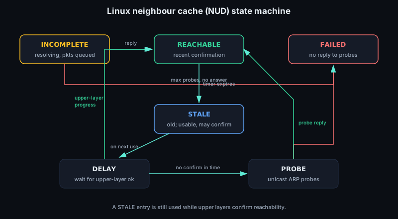
The ARP cache is a neighbor cache in the host stack, not a permanent truth. Linux's neighbour unreachability detection uses states that include INCOMPLETE, REACHABLE, STALE, DELAY, PROBE, and FAILED. INCOMPLETE means resolution is in progress and packets may be queued behind it. REACHABLE means the kernel has recent confirmation, often from a reply or from upper-layer progress such as TCP ACKs. STALE does not mean unusable; it means the mapping is old enough that the next use may start confirmation. DELAY gives upper layers a short chance to confirm reachability before active probes are sent. PROBE means unicast ARP probes are being sent to verify the mapping. The stack may continue using a stale mapping while it has upper-layer confirmation, or it may send probes before declaring the neighbor failed. A stale entry after a VM migration, NIC replacement, bonding failover, or IP takeover can send correct IP packets to the wrong destination MAC until the cache is refreshed. Gratuitous ARP and ARP announcements are used to update peers after movement, but filters, rate limits, or switch security features can suppress the signal. Proxy ARP is the deliberate version of a host or router answering ARP for an address that belongs elsewhere, making two IP subnets appear locally connected. ARP spoofing is the malicious or accidental version: a peer lies about an IP-to-MAC binding and attracts traffic. From a C program, send() can succeed because the packet was queued to the kernel even while neighbor resolution later fails; the error may appear asynchronously, through retransmission timeout, EHOSTUNREACH, or no useful error at all.
If the destination IP is not on the local subnet, ARP is still used, but for the router's MAC address rather than the final destination's MAC address. The IP packet keeps the remote destination IP, while the Ethernet frame is addressed to the default gateway. At each routed hop, the old Ethernet header is discarded and a new link-layer header is built. Switches move frames inside a LAN; routers move packets between LANs.
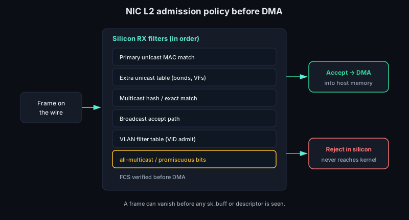
Putting it together, a frame crossing a LAN follows a short chain of decisions. The sender chooses the next-hop IP, resolves it to a MAC address if needed, builds an Ethernet frame with source MAC, destination MAC, optional VLAN tag, EtherType, payload, and FCS, and hands it to the NIC. Each switch learns the source MAC on the ingress port and VLAN, then forwards, floods, or filters based on the destination MAC and VLAN. The receiver's NIC accepts the frame if the destination MAC matches its unicast address, a multicast filter, broadcast, or promiscuous mode; hardware typically verifies the FCS before DMAing the packet into host memory.
A modern NIC therefore has its own L2 admission policy before the kernel ever sees an sk_buff or a user-space poll loop sees a descriptor. The device usually has a primary unicast MAC, a limited table of additional unicast addresses for bonds, bridges, VMs, or SR-IOV virtual functions, multicast hash or exact-match filters, a broadcast accept path, VLAN filter tables, and mode bits for all-multicast and promiscuous receive. VLAN acceleration can strip the 802.1Q header and place the VID and PCP into descriptor metadata; transmit offload can do the reverse. Kernel-bypass code must read the NIC manual here, not just the Ethernet RFCs: a frame missing from a capture may have been rejected by silicon before DMA, delivered to another VF, dropped by a VLAN filter, or accepted only because promiscuous mode disabled the normal filter path.
Filtering is the other half of forwarding. A bridge may drop a frame because the destination port is the same as the ingress port, because the VLAN is not admitted on the egress port, because the source MAC violates port-security policy, because storm control is limiting broadcast or unknown-unicast traffic, or because a multicast-snooping table has no interested receivers. Linux bridges, NIC switchdev devices, hypervisor vSwitches, and physical switches all expose variations of the same behavior. The important debugging rule is to locate the layer where the frame disappears: host transmit queue, NIC, access port, trunk, bridge table, egress port, target NIC filter, or target kernel receive path.
For low-level work, these details show up constantly. A driver may need to program unicast and multicast filters, enable promiscuous mode for capture, preserve or strip VLAN tags, report rx-vlan-offload metadata, or steer ARP and IP traffic to different receive queues. Offloads can confuse packet captures: a tag may be present on the wire but delivered as metadata, checksums may be completed after the capture tap, and receive hashing may place ARP, IPv4, and IPv6 neighbor traffic on queues that are not being inspected. A bad VLAN setting can make ARP look broken even though the PHY is up. A stale neighbor entry can make TCP look broken even though the NIC is transmitting. A too-small filter table can push the device into all-multicast or promiscuous mode. The LAN is "local" only at the IP level; underneath, it is precise MAC, VLAN, switching, and cache state.
Useful symptoms map directly to this machinery:
- Repeated ARP requests with no reply: wrong VLAN, target down, ingress filter, duplicate IP defense, or reply dropped on the return path.
- ARP replies visible in a switch capture but absent on the host: NIC filter, VLAN offload expectations, driver drop, bridge namespace, or capture on the wrong interface.
- First packet lost, later packets fine: neighbor resolution, unknown-unicast flooding, sleeping target, or a MAC table that had to be relearned.
- Traffic works one way only: asymmetric VLAN admission, stale neighbor cache on one endpoint, source MAC learning blocked, or a firewall above layer 2.
- Packets visible in promiscuous mode only: missing unicast filter programming, multicast filter overflow, wrong MAC address on the interface, or a virtual switch not tracking the guest MAC.
Sources
6.5 IP: addressing and routing
IP is the layer that lets a packet leave one local link and still have a meaningful destination. Ethernet can deliver a frame to a MAC address on the current LAN; IP names an interface in an internetwork and gives routers enough information to move the packet one hop at a time toward that name. The promise is deliberately modest: IP delivers datagrams, independently, best effort, with no built-in connection, retransmission, ordering, or congestion control.
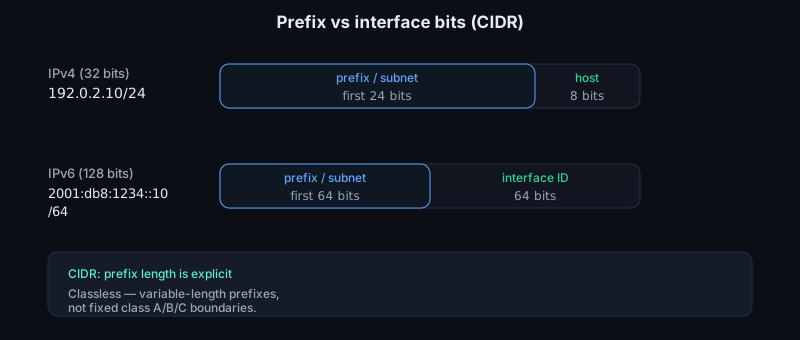
An IPv4 address is 32 bits, usually written as four decimal octets such as 192.0.2.10. An IPv6 address is 128 bits, written in hexadecimal groups such as 2001:db8::10. The important idea is the split between a prefix and the remaining interface bits. In 192.0.2.10/24, the first 24 bits identify the subnet; in 2001:db8:1234::10/64, the first 64 bits identify the IPv6 subnet. CIDR made this prefix length explicit and classless: forwarding decisions use variable-length prefixes, not old fixed class A/B/C boundaries.
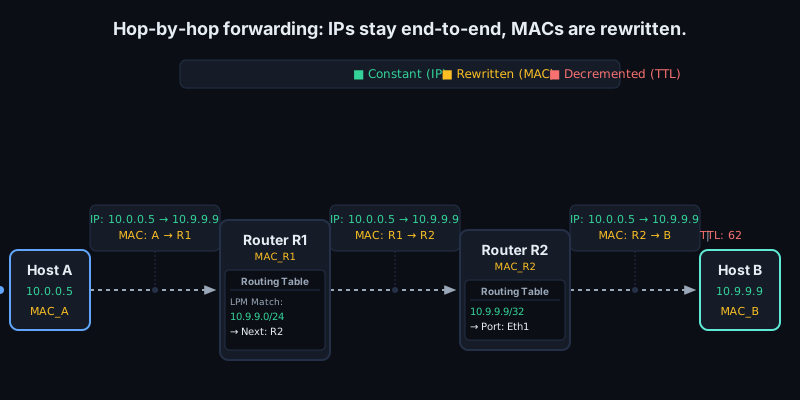
A host uses the prefix to decide whether a destination is local. If the destination address falls inside an on-link prefix, the host resolves a link-layer address for that destination and sends directly on the LAN. If not, it sends the packet to a router, usually the default gateway. The packet's IP destination remains the final destination; only the link-layer destination changes to the next hop's MAC address. A packet to 203.0.113.7 may therefore be carried in an Ethernet frame addressed to the local router.
That distinction is one of the key invariants in routed networking. Across ordinary forwarding, the layer-3 source and destination addresses are end-to-end values. At each hop, the router strips the incoming layer-2 frame, decides the next hop from the IP header, decrements the hop count field, and emits a new layer-2 frame for the next link. The Ethernet source MAC becomes the router's egress MAC, and the Ethernet destination MAC becomes the next hop's MAC. NAT, tunnels, and policy devices can deliberately violate or wrap this model, but plain routing does not rewrite the endpoint IP addresses.
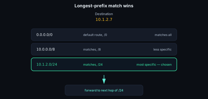
Routers do the same operation at scale. They inspect the destination IP address, choose the longest matching prefix in a forwarding table, and transmit the packet toward the selected next hop or outgoing interface. A route for 10.1.2.0/24 beats 10.0.0.0/8 because it is more specific. A default route, 0.0.0.0/0 or ::/0, matches only when nothing more specific does. Routing protocols decide how routes get installed; forwarding is the fast path that applies the chosen table.
It is useful to separate the RIB from the FIB. The routing information base is the control-plane view: connected routes, static routes, BGP or OSPF candidates, metrics, administrative preference, and policy. The forwarding information base is the data-plane structure derived from that view and optimized for lookup. In a kernel it may be a trie plus cached nexthop objects; in a router ASIC it may be TCAM, SRAM, or a compressed lookup pipeline. The correctness rule is still longest-prefix match, but the implementation is designed around cache locality, update cost, and packets per second rather than human readability.
The route lookup result is not just a yes-or-no answer. It usually carries an output interface, a next-hop address if the destination is not directly attached, a route type, a metric or priority, and sometimes policy state such as a routing table, mark, VRF, or source-address constraint. A host route, 192.0.2.10/32 or 2001:db8::10/128, is simply the most specific possible prefix. A connected route says "resolve the destination itself on this link." A gateway route says "resolve the next hop on this link." In both cases the next operation is neighbor discovery: ARP for IPv4, Neighbor Discovery for IPv6. If that resolution is pending, a kernel may queue a small number of packets, drop excess packets, or return an error depending on stack policy.
Longest-prefix match also explains why route ordering bugs are easy to miss. Human-readable route dumps may appear sorted by administrative preference, insertion order, or table, but the forwarding decision is by prefix length first, then by the implementation's tie breakers among otherwise equal routes. Equal-cost multipath adds another layer: the lookup may pick one next hop from a set by hashing packet fields so that most packets in a flow stay on the same path. The hash key is usually drawn from the same ideas as a NIC RSS key: source and destination IPs, transport ports when visible, and sometimes protocol, IPv6 flow label, or tunnel metadata. For NIC engineers, that means RSS, flow steering, and ECMP may all hash similar tuples at different points in the path. Small parser differences around fragments, extension headers, encapsulation, or whether the inner or outer tuple is used can change queue placement or path selection, which in turn changes cache affinity, packet ordering, and latency tails.
The IPv4 header starts at 20 bytes without options. It carries Version, IHL, differentiated-services bits, Total Length, Identification, fragmentation flags and offset, TTL, Protocol, a header checksum, and source and destination addresses. IHL is the Internet Header Length in 32-bit words, so the minimum valid value is 5 and the maximum header size is 60 bytes. That one nibble is why robust C code must compute the transport offset from the packet, not assume sizeof(struct iphdr) or a fixed byte 20. IPv4 options are uncommon on fast paths, but their mere possibility affects parsers, checksum offload setup, BPF programs, and packet capture code.
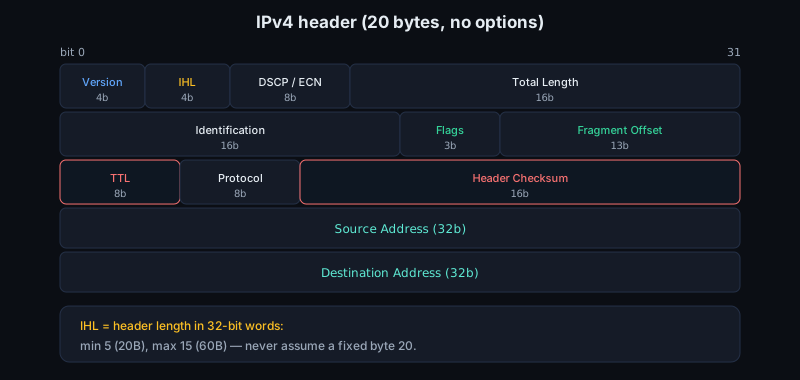
TTL is decremented by each router; at zero, the packet is discarded, normally with an ICMP time-exceeded error. The checksum covers only the IPv4 header, and RFC 791 is explicit that because fields such as time to live change, the header checksum is verified and recomputed at each point where the IP header is processed. Real forwarding code often updates it incrementally instead of summing the whole header again, but the semantic consequence is the same: IPv4 forwarding modifies the packet even when the endpoint addresses are preserved. IPv6 removed this header checksum, partly to avoid that per-hop work.
Protocol is an 8-bit demultiplexing field: 1 for ICMP, 6 for TCP, 17 for UDP, and many others. It is not a port number; ports live in the transport header, if the protocol has them and if the packet contains the relevant fragment. The IPv4 fragmentation fields are tightly connected to this. Identification is 16 bits. The flags include DF and MF, and the Fragment Offset is 13 bits in units of 8 bytes. A non-fragment has offset 0 and MF clear. A first fragment has offset 0 and may have MF set. Later fragments have a nonzero offset and usually do not contain TCP or UDP ports, so classifiers that claim a full five-tuple for them are either using saved state, making assumptions, or falling back to an IP-only key.
IPv6 simplified the base header to a fixed 40 bytes: version, traffic class, flow label, payload length, next header, hop limit, and 128-bit source and destination addresses. Options moved into extension headers, chained by Next Header. There is no IPv6 header checksum. Hop Limit is the IPv6 equivalent of IPv4 TTL.
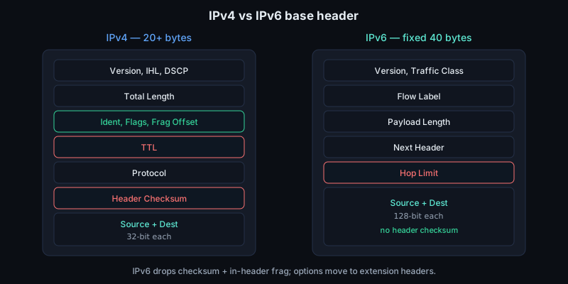
IPv6 also moved fragmentation out of routers. An IPv6 router that cannot forward a packet because of the next-link MTU drops it and reports the problem; it does not split the packet in transit. If an IPv6 source fragments, it uses a Fragment extension header and the destination reassembles. Extension headers make the base header regular, but they do not make parsing trivial: a fast path has to walk a bounded chain, recognize when the upper-layer header is absent or too deep, and handle the rule that most extension headers are processed only by endpoints, with Hop-by-Hop Options being the notable transit-router case.
The IPv4 and IPv6 differences are visible in hot code. IPv4's IHL means the transport header is not always at byte 20; options can move it. IPv6 has a fixed base header, but the first transport header may sit after zero or more extension headers, and only some extension headers are meant to be examined by transit routers. A software fast path must decide how far it is willing to parse before falling back. Hardware has the same problem with stricter limits: descriptor bits often say "IPv4," "IPv6," "TCP," "UDP," "fragment," or "checksum verified," but those bits only mean what the parser could actually prove within its supported header depth.
These fields matter in NIC and driver work because hardware parses just enough of the packet to accelerate common cases. Receive-side scaling may hash IP addresses and TCP/UDP ports into queues. Checksum offload depends on header offsets. Segmentation offload depends on the MTU and on correct header templates. A malformed IHL, unexpected IPv6 extension-header chain, fragment, or tunneled packet can push traffic off the fast path or expose bugs in descriptor metadata.
The MTU is the largest packet a link can carry at its network-layer boundary; classic Ethernet commonly carries an IP packet of 1500 bytes. If a datagram is larger than the next link's MTU, something must give. IPv4 permits routers to fragment a packet unless the DF flag says "do not fragment." When a router fragments IPv4, it copies the relevant header, uses the same source, destination, protocol, and identification value, sets offsets in 8-byte units, and sets MF on every fragment except the last. Reassembly happens at the destination, not at each router. Fragmentation is expensive and hostile to offloads because later fragments may not contain the transport header.
IPv6 is stricter: routers do not fragment packets. A source may use an IPv6 Fragment extension header, but fragmentation is done by the source and reassembly by the destination. IPv6 also requires every link in the internet path to support an MTU of at least 1280 octets. In practice, stacks try to avoid fragmentation by discovering the path MTU. For IPv4, Path MTU Discovery sends packets with DF set and listens for ICMP Destination Unreachable, code 4, the "fragmentation needed and DF set" case, ideally carrying the next-hop MTU. For IPv6, the analogous signal is ICMPv6 "Packet Too Big", type 2, code 0, with an MTU field. If those ICMP messages are blocked, small packets may work while bulk data stalls. That failure mode is the classic PMTUD black hole: connection setup and tiny requests succeed, then full-sized TCP segments, UDP datagrams, or encapsulated packets disappear until MSS clamping, smaller application payloads, or packetization-layer probing works around it.
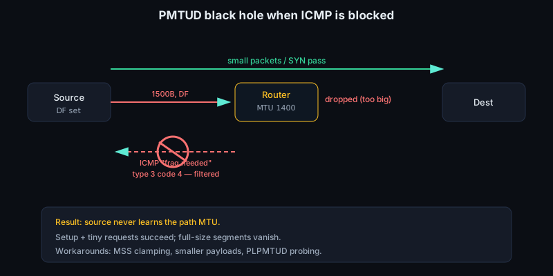
PMTU state is normally cached against a destination or flow and fed back into transport behavior. TCP can lower its segment size so that IP plus TCP headers fit under the discovered path MTU; UDP applications either send smaller datagrams, handle EMSGSIZE, or rely on application-level probing. TSO and GSO do not remove the MTU requirement. They let the host hand a large buffer to the stack or NIC, but the final wire packets still have to obey the egress MTU and the packetization rules for the IP version in use. A driver that advertises segmentation offload must therefore get header lengths, MSS, checksum start, checksum offset, and outer-versus-inner encapsulation fields exactly right.
Fragments are a special parser case, not just smaller packets. The first IPv4 fragment has offset 0 and usually contains the transport header; later fragments do not. IPv6 puts fragmentation metadata in an extension header, and the transport header may appear only in the first fragment. Firewalls, RSS classifiers, checksum offload, and flow dissectors either have to classify non-initial fragments on the IP tuple alone or punt them. Reassembly also has security and resource limits: overlapping IPv4 fragments, tiny fragments that split headers, and large fragment queues have historically exposed bugs in hosts and middleboxes.
ICMP is IP's control and error-reporting companion. It does not make IP reliable, but it tells senders why some datagrams could not be delivered or how forwarding behaved. Examples include echo request/reply for ping, destination unreachable, time exceeded for traceroute, and packet-too-big or fragmentation-needed messages for MTU discovery. ICMP errors quote enough of the offending packet for the sender to match the error to a flow. Treat ICMP as part of the data path: filtering it blindly can break PMTU discovery, and mishandling it can produce misleading socket errors or black holes.
ICMP handling is also part of correctness at the API boundary. A connected UDP socket may report asynchronous ICMP errors on a later send or receive. TCP treats some errors as soft hints and others as fatal depending on state and stack policy. Traceroute depends on routers generating time-exceeded messages after TTL or Hop Limit reaches zero, and PMTUD depends on packet-too-big messages carrying a usable MTU. Rate limiting is normal, because ICMP generation must not turn one bad stream into a control-plane flood, but complete suppression makes the network harder to debug and can break valid traffic.
The practical model is simple: addresses name endpoints, prefixes describe reachability, routes choose the next hop, and each hop rewrites only the local framing while preserving the packet's IP destination.
Sources
6.6 UDP and the datagram model
UDP is the transport layer at its most minimal. IP already gives a host a way to send one datagram toward another host; UDP adds just enough information to hand that datagram to the right application socket and detect corruption. It does not add a handshake, sequence numbers, acknowledgments, retransmission, ordered delivery, flow control, or congestion control. A UDP send is not "write these bytes into a stream." It is "send this one message as this one transport datagram."
That message boundary is the first difference from TCP. If an application sends 1200 bytes in one UDP operation, the receiver either receives one 1200 byte datagram, receives nothing, receives a truncated indication, or receives an error from the stack. UDP does not merge adjacent sends into a byte stream, and a normal recvmsg consumes at most one datagram. If the receive buffer is too small, the excess bytes are discarded; on Linux, MSG_TRUNC can report the original length. A zero-length UDP payload is also valid. For C code, the buffer length is not a flow-control hint, and a short receive is not the first slice of a later record.
UDP therefore suits protocols whose natural unit is already a message: a DNS query, an NTP packet, a game-state update, a media packet, a QUIC packet, or one outer packet in a tunnel. It is also unforgiving when an application secretly wanted a reliable byte stream. Reordering, duplication, loss, and bursts are ordinary outcomes, not exceptional cases. A protocol using UDP should make the packet boundary meaningful and cheap to validate.
Because UDP has no receive window or congestion window, the sender is not naturally slowed by the receiver or by the path. A tight loop around sendmmsg can create line-rate bursts until socket buffers, qdisc limits, NIC rings, switch buffers, or the remote host drop packets. Serious UDP protocols therefore carry their own pacing and recovery logic, or delegate it to a library: sequence numbers, timestamps, acknowledgments or negative acknowledgments, retransmission policy, forward error correction, congestion response, and application-level backpressure. For interview-level systems work, this is often the real distinction: UDP removes transport machinery from the kernel protocol, but it does not remove the need to be a good network citizen.
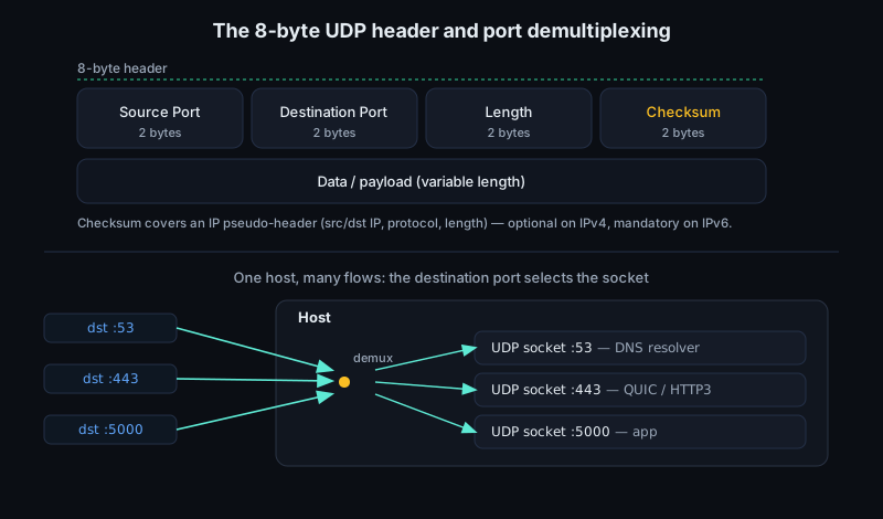
The UDP header is always 8 bytes:
- source port:
16bits - destination port:
16bits - length:
16bits, covering UDP header plus payload - checksum:
16bits
In memory you usually avoid casting packet bytes directly to a C struct unless alignment, bounds, and byte order are already controlled, but the wire layout is this simple:
struct udp_wire {
    uint16_t src_port;
    uint16_t dst_port;
    uint16_t len;
    uint16_t check;
};
All four fields are in network byte order. len is the UDP datagram length, not the IP packet length, so it repeats information that is also derivable from the enclosing IP header in ordinary packets. That redundancy is useful: it gives the transport layer an explicit bound for checksum calculation and receive validation, and it matters when a driver or parser is walking raw DMA buffers rather than trusting a higher-level socket abstraction.
The length field means the largest UDP payload in an IPv4 packet with no IP options is 65507 bytes: 65535 bytes of IPv4 total length, minus 20 bytes of IPv4 header, minus 8 bytes of UDP header. That is a protocol maximum, not a good operational size. Ethernet with a common 1500 byte MTU leaves 1472 bytes for UDP payload over IPv4, or 1452 over IPv6. Add VLAN tags, PPPoE, IPsec, WireGuard, VXLAN, Geneve, or another tunnel and the usable inner payload falls again. Good UDP protocols stay below the path MTU, discover it, or implement loss recovery above UDP.
Ports are UDP's demultiplexing names. An IP packet reaches a host; the IP Protocol value 17 says the payload is UDP; the UDP destination port selects the receiving socket. A server may bind 53/udp for DNS or 123/udp for NTP. A client usually uses an ephemeral source port so replies can be matched back to the client socket. Stacks often identify a UDP socket by local and remote addresses and ports, with wildcard rules for unconnected sockets. The most specific matching socket normally wins before a wildcard bind. Once both endpoints are known, the logical UDP flow is the familiar 4-tuple: source IP, source port, destination IP, destination port. Many NIC classifiers and RSS hash functions also include the IP protocol number, making a 5-tuple for steering.
A "connected" UDP socket records a default peer and filters incoming datagrams; it does not create a transport connection. There is no SYN, no peer state in the network, and no remote consent. In kernel terms, connect caches the remote tuple, often selects the local source address and ephemeral port, and lets the application use send or write. It also tightens lookup and error delivery: packets and ICMP errors that do not match the recorded peer can be ignored. Reconnecting or disconnecting such a socket is a local operation, not a protocol exchange.
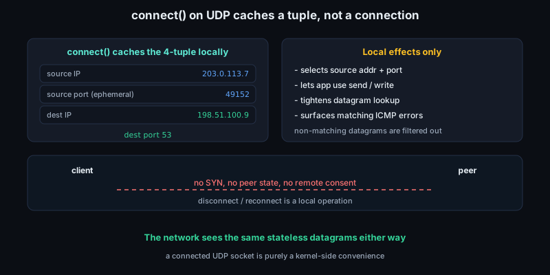
If no socket is listening on the destination port, the packet is not queued. A host may send ICMP Destination Unreachable, Port Unreachable, or the analogous ICMPv6 error. Path problems may also arrive through ICMP: IPv4 "fragmentation needed" and ICMPv6 Packet Too Big report that a datagram exceeded the path MTU. Firewalls, rate limits, NATs, and host policy can suppress or rewrite these errors, so absence of an error is not proof of delivery. On Linux, connected UDP sockets commonly surface relevant ICMP errors on later socket operations, and extended error queues can expose more detail when enabled. None of this upgrades UDP into reliable delivery.
The checksum is more subtle than its 16 bits suggest. UDP computes the one's-complement checksum over the UDP header, payload, and a pseudo-header containing the source IP address, destination IP address, protocol number, and UDP length. In IPv4, that pseudo-header is 12 bytes: 32 bits of source address, 32 bits of destination address, 8 zero bits, 8 bits of protocol, and 16 bits of UDP length. In IPv6, the addresses are 128 bits each and the pseudo-header uses the IPv6 next-header value and an upper-layer packet length. The pseudo-header is not transmitted; it binds the checksum to the IP endpoints so some misdelivery or header corruption is caught. This is a deliberate cross-layer dependency: a UDP checksum cannot be validated from the UDP bytes alone, and a kernel-bypass receive path needs the relevant L3 fields before it can honestly mark L4 good. Odd-length payloads are padded with a zero byte for checksum calculation only. For IPv4, UDP checksum value 0 means "no checksum was computed," although modern stacks normally compute it. If the computed checksum itself would be zero, it is transmitted as all ones. For IPv6, normal UDP packets must carry a nonzero checksum; zero-checksum mode exists only for tightly constrained tunnel cases where the endpoints and failure modes are explicitly controlled.
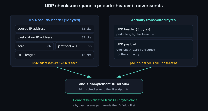
Checksum offload makes this relevant to low-level work. On transmit, the kernel may build an sk_buff with CHECKSUM_PARTIAL, set csum_start to the transport header, set csum_offset to the checksum field, and rely on the NIC to finish the checksum after DMA. A capture above the device may show a bogus checksum even though the wire packet is correct. On receive, hardware reports descriptor status, which the driver translates into CHECKSUM_UNNECESSARY, CHECKSUM_COMPLETE, or a software fallback. Bugs in header offsets, VLAN stripping metadata, tunnel parsing, checksum-level accounting, or fragments can turn a correct datagram into a checksum error, or worse, mark a bad one as good.
UDP offloads differ from TCP. TCP segmentation offload can split a byte stream because sequence numbers and per-segment checksums define valid segments. A large UDP datagram is still one datagram; if it exceeds the path MTU, the result is IP fragmentation, local EMSGSIZE, or a UDP-aware segmentation feature. With Linux UDP GSO, a large buffer plus segment size becomes multiple UDP datagrams with the same 5-tuple and separate length and checksum fields. gso_size, gso_segs, and the UDP GSO type are batching metadata, not proof of a jumbo UDP packet on the wire.
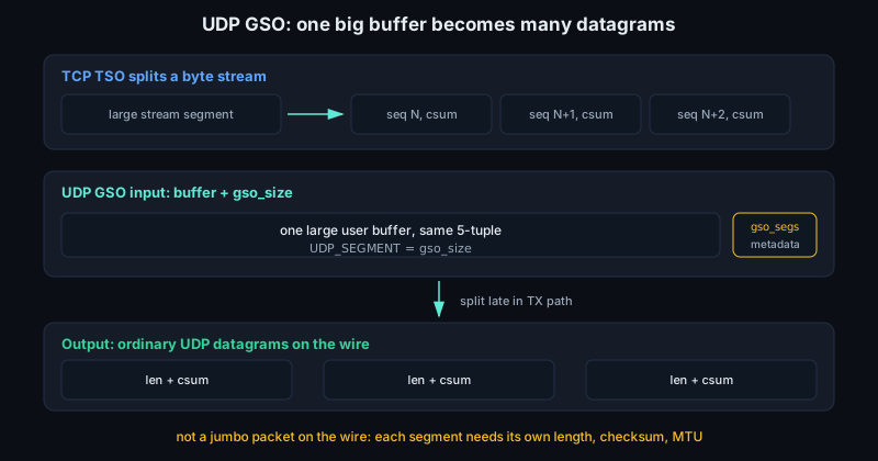
The point of UDP GSO is not to make UDP reliable or larger; it is to amortize per-packet work for high-packet-rate workloads. A user process can hand the kernel a larger buffer and a segment size, often through the UDP_SEGMENT ancillary data path, and the stack or NIC can produce many ordinary UDP packets late in the transmit path. That saves syscall, routing, qdisc, allocation, and descriptor overhead. It is especially valuable for telemetry, media, tunnel endpoints, load balancers, and RPC systems that want small wire packets but cannot afford one full software trip per packet. The sharp edge is that every produced segment still needs a correct UDP length, checksum, and MTU decision.
UDP GRO is receive-side batching. It can coalesce adjacent datagrams from the same flow into one larger packet buffer, with metadata preserving the segment size. This amortizes overhead, but checksum state, hash state, timestamps, VLAN tags, and tunnel metadata must remain honest for every member. User-space that enables UDP GRO must read the control message carrying segment size, or it can mistake a batch for a protocol record. The UDP boundary still exists, but the host may represent several records with one internal buffer.
Fragmentation is the slow and fragile alternative to segmentation. IPv4 routers may fragment unless the Don't Fragment bit forbids it; IPv6 routers do not fragment forwarded packets. Losing one fragment loses the whole UDP datagram. Later fragments usually do not carry the UDP header, so port-based firewalls, RSS classifiers, BPF programs, and NIC flow steering need reassembly state or conservative decisions. Fragments are hostile to tunnels because outer or inner fragmentation hides headers from offload. Operational UDP protocols generally avoid IP fragmentation rather than depending on it.
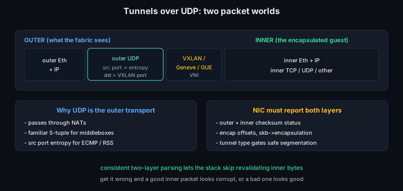
Tunnels use UDP because it passes through NATs, gives middleboxes a familiar 5-tuple, and lets the outer source port carry entropy for ECMP and RSS. VXLAN, Geneve, GUE, and many VPN designs rely on that property. The cost is two packet worlds: outer Ethernet/IP/UDP headers and inner headers that may contain TCP, UDP, or something else. A NIC or driver advertising tunnel checksum, tunnel segmentation, or inner RSS support must parse and report both layers consistently. Outer and inner checksum status, encapsulation offsets, skb->encapsulation, and tunnel type decide whether the stack can avoid revalidating bytes or legally segment an encapsulated packet.
The same substrate pattern appears in low-latency datacenter and accelerator fabrics. RoCEv2 carries RDMA over UDP/IP so it can route at layer 3 while still exposing queue-pair semantics above the network layer. Many HPC and AI transports use UDP-like packetization because they want user-space control, NIC steering, loss detection tuned to a controlled fabric, or compatibility with ECMP fabrics and kernel-bypass queues. That does not mean "UDP is fast" by itself. The performance comes from the surrounding system: preposted buffers, huge receive rings, interrupt moderation or polling, hardware timestamping, RSS or flow director rules, congestion control appropriate to the fabric, and careful avoidance of drops. UDP is attractive because it is a narrow waist that NICs, switches, kernels, and middleboxes already understand.
QUIC is the clearest modern example of "UDP as substrate, not UDP as complete service." QUIC uses UDP datagrams to carry encrypted packets, but implements connection setup, stream multiplexing, acknowledgments, loss recovery, congestion control, path validation, and migration above UDP. Its connection IDs avoid depending only on the 4-tuple, because NAT rebinding or mobility can change addresses and ports while the logical connection survives. QUIC still has to respect datagram boundaries, anti-amplification limits, PMTU constraints, and checksum behavior.
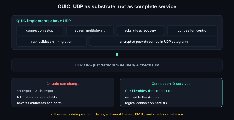
UDP is the right choice when the application wants datagrams, can tolerate loss or handle it itself, and values simple framing, low setup cost, multicast, broadcast, NAT traversal, or custom control over retransmission and timing. DNS, DHCP, NTP, RTP media, QUIC, telemetry, and tunnels use UDP for versions of this reason. UDP is wrong if an application assumes reliable ordered bytes but forgets to build reliability, congestion control, path MTU handling, replay protection, and security above it. The absence of TCP machinery is power, not magic: it moves responsibility upward and exposes more of the network's real behavior to the program.
Sources
- RFC 768: User Datagram Protocol
- RFC 1122: Requirements for Internet Hosts - Communication Layers
- RFC 8200: Internet Protocol, Version 6 Specification
- RFC 8085: UDP Usage Guidelines
- RFC 8899: Packetization Layer Path MTU Discovery for Datagram Transports
- RFC 9000: QUIC: A UDP-Based Multiplexed and Secure Transport
- Linux kernel documentation: Segmentation Offloads
- Linux kernel documentation: Checksum Offloads
- Linux udp(7) manual page
- RFC 7348: Virtual eXtensible Local Area Network
- RFC 6936: Applicability Statement for IPv6 UDP Datagrams with Zero Checksums
6.7 TCP: reliability and control
TCP exists because IP gives only best-effort packet delivery. Packets may be lost, duplicated, reordered, or delayed. TCP turns that service into a reliable, ordered, full-duplex byte stream by keeping state at the endpoints and using feedback from the receiver.
A TCP connection is identified by the four-tuple of source address, source port, destination address, and destination port. Before data can flow, both endpoints must agree on initial sequence numbers and prove that the peer can receive packets on this path. The usual three-way handshake is SYN, SYN-ACK, ACK. If the client chooses initial sequence number x, its SYN consumes sequence number x, so the server acknowledges x + 1. The server chooses its own initial sequence number y in the SYN-ACK, and the client acknowledges y + 1. This is why a connection has two independent sequence spaces: one for each direction of the full-duplex stream.
SYN and FIN each consume one sequence number even when they carry no payload. A pure ACK does not. Data consumes one sequence number per byte. The sequence fields are 32-bit values and can wrap, so kernel code treats comparisons as modular sequence arithmetic, not ordinary unsigned integer ordering. The receive window is also expressed in this sequence space: a segment is acceptable only if at least part of its byte range falls inside the current window. This is the low-level reason that off-by-one bugs around SND.UNA, SND.NXT, RCV.NXT, and the advertised window create visible stalls, duplicate ACKs, or unexpected resets.
static inline int before(uint32_t a, uint32_t b) { return (int32_t)(a - b) < 0; }
static inline int after(uint32_t a, uint32_t b)  { return before(b, a); }
The visible socket states are a practical debugging map of this protocol state. A passive opener sits in LISTEN. An active opener sends SYN and enters SYN-SENT. The server that has received a SYN and replied with SYN-ACK is in SYN-RECEIVED. Once the final ACK is accepted, both sides are ESTABLISHED. Teardown is also stateful: each direction is closed with a FIN, and the side that sends the final acknowledgment typically remains in TIME-WAIT so delayed duplicates from the old connection cannot be confused with a later one using the same four-tuple. In low-level work, these states explain SYN queue overflow, backlog limits, reset storms, and sockets stuck in TIME-WAIT: TCP’s state machine is becoming visible.
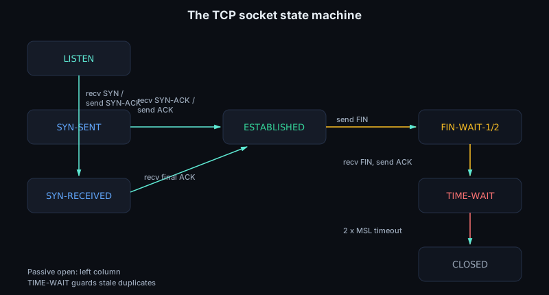
Half-close states matter in production traces. Receiving FIN before the local application closes leaves CLOSE-WAIT; sending FIN moves through FIN-WAIT-1 and FIN-WAIT-2. LAST-ACK waits for the final ACK after the local FIN; CLOSING appears under simultaneous close. RST aborts state and tells the peer to stop using that sequence space.
Reliability is built on sequence numbers and acknowledgments. TCP numbers bytes, not packets. A segment carrying 1000 bytes starting at sequence 5000 covers byte positions 5000 through 5999; the receiver’s cumulative ACK 6000 means “I have received everything before byte 6000 and need 6000 next.” If a later segment arrives but byte 6000 is missing, the receiver keeps acknowledging 6000. Duplicate ACKs are therefore a signal that something after the last in-order byte may have arrived while a gap remains.
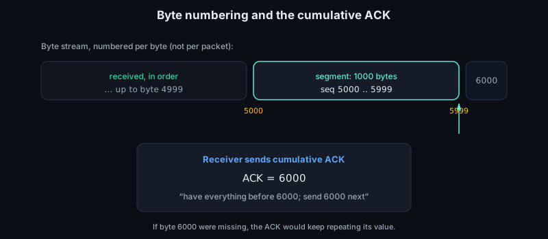
ACK behavior is intentionally conservative. Delayed ACK can wait briefly so one ACK covers two full-sized segments or piggybacks on outbound data. A selective acknowledgment option can report received out-of-order blocks, but the ordinary ACK number remains cumulative and cannot advance across a hole. ACKs also clock the sender: each advancing ACK proves that data left the network and buffer space opened at the receiver. Reordering, GRO flush boundaries, LRO behavior, asymmetric paths, or a receive queue mapped to the wrong CPU can change ACK patterns without changing application data.
SACK is negotiated explicitly. The SACK-permitted TCP option is kind 4, length 2, and is valid only on SYN segments; after that, ACKs may carry SACK blocks using option kind 5. Each SACK block is a pair of 32-bit sequence numbers: the left edge is the first byte received in that out-of-order block, and the right edge is the first byte after the block. The cumulative ACK still says where the first hole begins. The sender therefore keeps more than a FIFO retransmit list: it annotates the retransmission queue with which byte ranges are cumulatively ACKed, SACKed, retransmitted, or still suspected lost. With SACK, the sender can retransmit holes while avoiding data the receiver already queued. SACK is advisory because the receiver may later discard queued out-of-order data under memory pressure, so robust senders must still handle reneging.
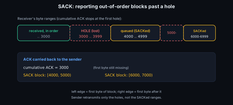
The sender keeps transmitted but unacknowledged data in memory because it may need to retransmit it. If an ACK advances, the sender can free the acknowledged bytes. If a retransmission timeout fires, the sender sends the missing data again. Modern TCP computes the timeout from measured round-trip time, maintaining a smoothed RTT and variation estimate; RFC 6298 specifies an initial RTO of 1 second before any RTT sample, with backoff after repeated loss. Most stacks avoid RTT samples from retransmitted data unless TCP timestamps identify which transmission was acknowledged. This is Karn's rule in practice: a bad sample can poison the RTO and create needless retransmits or long stalls. Fast retransmit is the shorter feedback path: when duplicate ACKs strongly imply a missing segment, traditionally after about three duplicate ACKs, the sender can retransmit before the timer expires. Fast recovery then tries to keep the ACK clock running instead of dropping all the way back to slow start: it reduces the congestion window, retransmits what appears missing, and uses incoming ACKs as evidence that packets are still leaving the network.
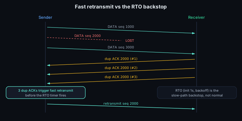
Modern loss detection is less purely "count duplicate ACKs and wait." RACK-TLP uses transmit timestamps and ACK/SACK feedback to infer that a packet is lost when sufficiently newer data has been delivered. That is a better fit for reordering, small flights, application-limited bursts, or lost tail packets where there may not be enough later packets to produce three duplicate ACKs. Tail Loss Probe sends a small probe near the end of a flight to elicit ACK feedback and avoid a full retransmission timeout. The retransmission timer is still the backstop, but should be the slow path, not the normal loss detector. The retransmission timer is distinct from the persist timer used for zero-window probing and from keepalive machinery used to discover dead idle peers.
For a NIC or driver engineer, these timers make timestamping, interrupt moderation, drops, checksum status, and receive ordering part of transport behavior. Hardware or software timestamping can expose serialization delay, queueing delay, and ACK compression, but it can also move the apparent receive time depending on whether the timestamp is taken at the MAC, driver, NAPI poll, socket enqueue, or userspace read. Interrupt coalescing reduces CPU cost by batching completions, yet it adds variance to ACK generation and RTT samples. A driver that loses a receive completion or misreports a checksum can make the transport infer congestion or corruption and collapse throughput far above the driver layer.
Flow control is separate from reliability. The receiver advertises a receive window, saying how many more bytes beyond the acknowledged sequence it is prepared to accept. This prevents a fast sender from overrunning a slow receiver’s socket buffer. The sender may have more application data ready, but it cannot have more unacknowledged data in flight than the advertised window allows. This is the sliding window: as ACKs advance, the left edge moves forward; as the receiver advertises more space, the right edge can move forward. A zero window means the receiver is temporarily out of buffer space, not that the route has failed.
The TCP header carries a 16-bit window field, which is too small for high bandwidth-delay paths. Window scaling, negotiated only in the SYN exchange, shifts that field left by a fixed per-direction scale factor for the life of the connection. If the option is stripped or not enabled during the handshake, the connection cannot grow the advertised window beyond the unscaled limit later. This is separate from autotuning: the kernel may resize socket buffers and choose larger advertised windows at runtime, but only within the scale negotiated at open. When the advertised window reaches zero, the sender uses small probes so it can learn when space reappears even if the receiver's window update is lost.
Congestion control answers a different question: even if the receiver has buffer space, how much data can the network path carry without building queues until packets are dropped? Classic TCP keeps a sender-side congestion window, cwnd. The usable flight limit is roughly the smaller of the receive window and cwnd. At the start of a connection, TCP uses slow start: cwnd grows rapidly as ACKs return, probing for capacity. After a threshold, congestion avoidance uses additive increase: grow cwnd by about one maximum segment size per round-trip time. When loss is inferred, TCP treats it as congestion and reduces the sending rate. The classic AIMD rule is additive increase, multiplicative decrease: probe upward gently, then cut back sharply, commonly setting a new slow-start threshold to about half the current flight size.
Reno is the reference model for this AIMD behavior, but it is not the common high-performance Linux behavior on modern systems. Linux's usual default is CUBIC, standardized in RFC 9438, which uses a cubic function of time since the last congestion event rather than Reno's linear increase. CUBIC is still loss-based: loss, ECN feedback, or modern loss detection tells it that it has pushed too far. BBR is model-based, estimating bottleneck bandwidth and round-trip propagation time instead of treating loss as the primary signal.
ECN lets the network signal congestion without first dropping a packet. The ECN field is the low two bits of the IPv4 TOS byte or IPv6 Traffic Class octet: 00 is Not-ECT, 10 is ECT(0), 01 is ECT(1), and 11 is CE for Congestion Experienced. An ECN-capable sender marks packets with an ECT codepoint; an active queue management device can change ECT to CE instead of dropping the packet. The receiver echoes that mark with the TCP ECE flag, and the sender reduces cwnd and sets CWR to say it has reacted. For driver and kernel-bypass work, congestion is not identical to checksum errors or missing descriptors: a packet can arrive intact and still make the sender slow down.
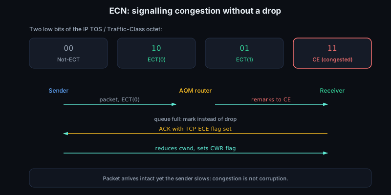
AIMD also explains why raw link speed is not the whole performance story. Throughput depends on the data allowed in flight, which must be large enough to cover the bandwidth-delay product. A 100 Gbit/s path with 100 us RTT has a BDP of about 1.25 MB; with 10 ms RTT it is about 125 MB. If SO_SNDBUF, SO_RCVBUF, autotuning limits, or the negotiated window scale cap the connection below the BDP, the NIC can go idle. Excessive queueing creates latency and loss that force TCP to reduce cwnd. A receive-window limit looks like application or socket-buffer back pressure; a congestion-window limit looks like path probing and loss response. The fix is different, so tools such as ss -ti, packet captures, NIC counters, and retransmit counters are most useful when they distinguish rwnd, cwnd, drops, and application read rate.
Small writes have their own latency trap. Nagle's algorithm reduces tiny packets by holding a partial segment while earlier data is unacknowledged. Delayed ACK waits briefly before acknowledging. Together they can create stalls: the sender waits for an ACK before sending the next small write, while the receiver waits in case it can combine or piggyback the ACK. Latency-sensitive protocols often set TCP_NODELAY to disable Nagle; bulk protocols may prefer TCP_CORK or batching so headers and payload leave as full segments.
Checksum offload, TSO/GSO, GRO/LRO, RSS, and pacing all sit near this boundary: they reduce CPU cost and smooth packet movement, but must preserve TCP’s byte-stream semantics, ordering assumptions, and feedback signals. With TSO or GSO, the stack may hand a large buffer to the NIC or lower layer after choosing sequence ranges; the wire still contains ordinary TCP segments with correct sequence numbers and checksums. A capture above segmentation may show one large skb that never existed on the wire; a switch mirror shows the actual MSS-sized segments. GRO or LRO may merge received segments before the stack or capture point sees them, hiding wire packet boundaries and changing when cumulative ACKs are generated. RSS should keep all packets for one TCP flow on one receive queue unless the NIC supports careful reordering protection; spreading one sequence space across queues can manufacture reordering above the hardware. Hardware timestamps can show wire arrival time while software timestamps may show NAPI, socket enqueue, or userspace observation time. Pacing and byte queue limits keep a fast host from dumping a large TSO burst into a shallow device queue and turning TCP's smooth ACK clock into a clump of packets.
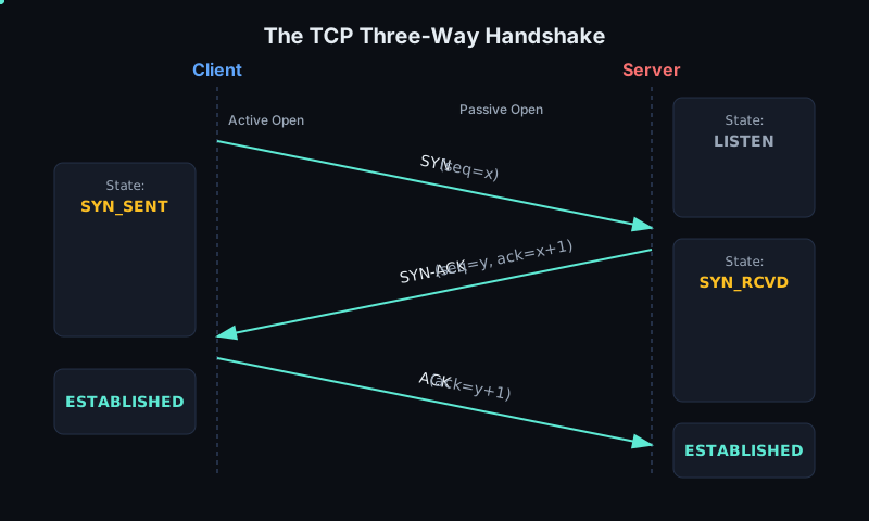
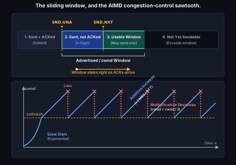
Sources
- RFC 9293: Transmission Control Protocol (TCP)
- RFC 6298: Computing TCP's Retransmission Timer
- RFC 5681: TCP Congestion Control
- RFC 7323: TCP Extensions for High Performance
- Van Jacobson, Congestion Avoidance and Control
- RFC 2018: TCP Selective Acknowledgment Options
- RFC 8985: The RACK-TLP Loss Detection Algorithm for TCP
- RFC 3168: The Addition of Explicit Congestion Notification to IP
6.8 The socket API and the data path
To an application, the network is not an Ethernet frame or an IP packet. It is a file descriptor. A socket is the operating system object that gives user code a controlled handle on the protocol stack: the process asks the kernel for an endpoint, describes what kind of traffic it wants, and then moves bytes or datagrams through system calls. The kernel owns the routing table, neighbor cache, TCP state machine, retransmission timers, congestion control, packet queues, and driver interface. The application owns intent: where to connect, what local address or port to use, and what data to send.
The first call is usually socket(domain, type, protocol). For ordinary IP networking, domain is AF_INET or AF_INET6. The type is commonly SOCK_STREAM for TCP or SOCK_DGRAM for UDP. The protocol is often 0, meaning "choose the default protocol." The return value is a file descriptor, so normal descriptor rules apply: close releases it, fcntl can set flags, descriptor passing can move it between processes, and readiness APIs can wait for activity. At creation time the socket is mostly policy and bookkeeping: protocol family, type, credentials, namespace, marks, options, and empty queues. It becomes a network endpoint only as later calls attach addresses, peers, or packet filters.
The address argument model is deliberately generic. Calls such as bind, connect, accept, getsockname, and getpeername take struct sockaddr * plus a socklen_t, but real code usually fills a domain-specific object such as struct sockaddr_in for IPv4 or struct sockaddr_in6 for IPv6 and casts its address at the call boundary. The common first field is the address family, so the kernel can interpret the bytes correctly. When writing library code that may receive either IPv4 or IPv6, use struct sockaddr_storage; it is sized and aligned to hold any supported socket address. The cast is not an object-oriented hierarchy. It is a C ABI convention: "here is a byte layout, and here is its length."
bind assigns a local address to the socket. Servers bind because clients need a stable destination, such as 0.0.0.0:443 or [::]:53. Clients often do not bind explicitly; on connect, the kernel chooses a source address from the route and an ephemeral source port. Binding to 0.0.0.0 means "any local IPv4 address," not "the whole Internet." Binding to 127.0.0.1 keeps the service on loopback, so packets never reach the NIC.
For TCP servers, listen changes a bound stream socket into a passive endpoint. It does not create a connected socket and it does not accept data. It tells the TCP stack to match incoming SYNs for that local address and port, run the handshake, and place completed children on an accept queue. The backlog argument is not a general packet buffer; it constrains connection admission around the SYN queue and accept queue, with details depending on kernel settings such as SYN cookies. accept removes one completed child and returns a new file descriptor. The listening descriptor remains open for more handshakes, while the accepted descriptor has its own TCP state, socket buffers, options, and readiness. If the application stops calling accept, the accept queue fills even if the NIC and protocol stack are still receiving packets correctly.
The canonical TCP server sequence is socket, optional setsockopt, bind, listen, then a loop around accept or accept4. The canonical TCP client sequence is socket, optional bind if the client needs a specific source address or port, then connect. On Linux, accept4(..., SOCK_NONBLOCK | SOCK_CLOEXEC) is often preferable to accept followed by two separate fcntl calls, because the accepted descriptor is born with the intended flags.
int lfd = socket(AF_INET6, SOCK_STREAM | SOCK_NONBLOCK | SOCK_CLOEXEC, 0);
struct sockaddr_in6 addr = { .sin6_family = AF_INET6,
                             .sin6_port = htons(8080) };
int one = 1;
setsockopt(lfd, SOL_SOCKET, SO_REUSEADDR, &one, sizeof(one));
bind(lfd, (struct sockaddr *)&addr, sizeof(addr));
listen(lfd, SOMAXCONN);
for (;;) {
    int cfd = accept4(lfd, NULL, NULL, SOCK_NONBLOCK | SOCK_CLOEXEC);
    if (cfd >= 0) handle(cfd);
    else if (errno == EAGAIN || errno == EWOULDBLOCK) break;
    else die("accept4");
}
High-rate servers often add SO_REUSEPORT before bind. With every participating socket setting the option and binding the same local address and port, the kernel can distribute incoming TCP connections or UDP datagrams across a reuseport group. That lets one listener per worker thread or process accept work without a single shared accept lock becoming the first scalability limit. It also maps naturally onto NIC receive-side scaling: flows can be steered by hash to queues, softirq work can run on nearby CPUs, and the application can keep per-core state hot in cache. A reuseport BPF program can override the default selection policy when the application wants explicit sharding.
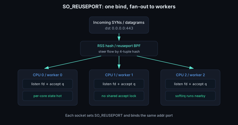
connect means different things for TCP and UDP. For TCP, it starts connection establishment: the kernel sends SYN, waits for SYN-ACK, replies with ACK, and then exposes a usable byte stream. For UDP, there is no transport handshake. A connected UDP socket records a default peer and filters incoming datagrams to that peer, allowing send and recv instead of sendto and recvfrom. In both cases, connect also forces a routing decision: outgoing interface, next hop, source address, and immediate errors such as "network unreachable."
For UDP, the unconnected sequence is just socket, optional bind, then sendto and recvfrom. A server usually binds so clients have a destination port; a client may let the first send choose an ephemeral port. A connected UDP socket uses socket, optional bind, connect, then send and recv, but this is still a datagram socket: there is no SYN, no accept queue, no byte stream, and no transport-level retransmission.
After setup, send copies data from user memory into kernel socket buffers. For TCP, those bytes enter a stream. The kernel may segment them later according to the MSS, congestion window, receiver window, pacing, qdisc policy, and offload settings. A successful send usually means the kernel accepted the bytes, not that the peer received them and not that the NIC has DMAed them. For UDP, each send normally corresponds to one datagram, subject to size and MTU limits. recv moves data back to user memory. TCP returns an ordered byte stream with no application message boundaries. UDP returns one datagram at a time; if the user buffer is too small, the excess payload is discarded unless the caller asks for truncation reporting.
The richer socket calls are sendmsg and recvmsg. Their struct msghdr contains an array of struct iovec, so one system call can gather bytes from several user buffers or scatter received bytes into several buffers. That matters in low-level C because a protocol header, payload, and trailer can remain in separate allocations while the kernel sees one logical send. The same interface carries ancillary data such as timestamps, packet info, file descriptors for Unix sockets, and error-queue notifications. MSG_ZEROCOPY extends send, sendto, sendmsg, and sendmmsg so large sends can avoid copying user bytes into kernel-owned memory after the socket has opted in with SO_ZEROCOPY. It is not free: pages are pinned, completions arrive on the socket error queue, and the application must not reuse the buffer until the kernel reports that it is safe. For small writes, the bookkeeping can cost more than the copy.
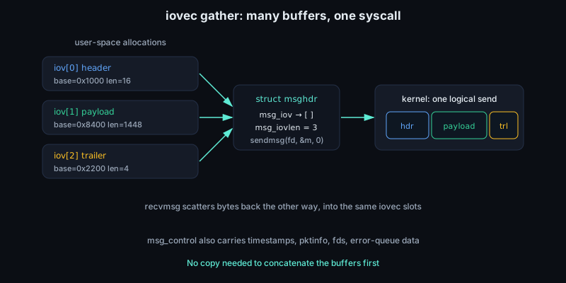
The end of the lifecycle matters. shutdown(SHUT_WR) on TCP sends FIN after queued data, leaving the receive side open for the peer's remaining bytes. close drops the file descriptor reference; the socket may live longer while TCP drains data, retransmits, waits in TIME_WAIT, or sends a reset if unsent data is discarded. SO_LINGER changes close behavior but does not turn TCP into a record protocol. For UDP, close mostly releases local state and queued datagrams. For both TCP and UDP, descriptor lifetime, protocol lifetime, and NIC queue lifetime are related but not identical.
The simplest socket is blocking. If a TCP recv has no bytes available, the calling thread sleeps. If a send cannot fit more data into the socket send buffer, it sleeps. This model is clear, but it scales poorly when thousands of mostly idle connections exist. Setting O_NONBLOCK with fcntl, or asking for SOCK_NONBLOCK at creation on Linux, changes the contract: calls that would sleep fail immediately with EAGAIN or EWOULDBLOCK. POSIX allows either name for this condition and does not require the constants to have the same value, so portable code checks both. The application then needs a way to sleep until at least one descriptor can make progress.
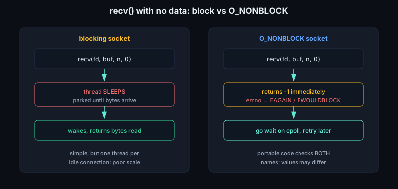
The older readiness interfaces are select and poll. select uses fixed-size descriptor sets and is awkward once descriptor numbers grow. poll takes an array of struct pollfd, removing the fixed bitmap limit but still making the kernel scan the caller's array each time. On Linux, epoll is the usual scalable readiness mechanism. An application creates an epoll instance, registers socket descriptors and event masks, then calls epoll_wait. A readable TCP socket may have bytes queued, a completed incoming connection, EOF, or an error. A writable socket usually means some send-buffer space exists, not that the network is fast or the peer is healthy. Level-triggered epoll keeps reporting readiness while the condition remains true. Edge-triggered epoll reports transitions, so the program must use nonblocking descriptors and drain recv, send, or accept until EAGAIN or it may miss progress. The rule is simple and unforgiving: with EPOLLET, do the work until the syscall says it would block, then return to epoll_wait.
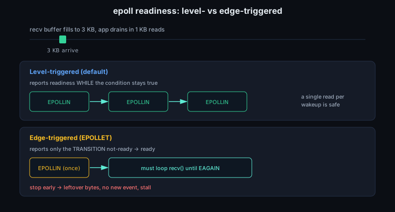
Readiness is about whether a system call can make local progress. It is not a delivery guarantee and it is not an interrupt from the NIC. EPOLLIN on a listening socket means accept should succeed unless another thread wins the race. EPOLLIN on a TCP stream can mean payload, FIN, RST, or a pending socket error readable through SO_ERROR. EPOLLOUT on a nonblocking connect means the connection finished or failed; the program must check getsockopt(SO_ERROR). A socket can be readable and writable at the same time, and error or hangup conditions are reported even if the application did not request them.
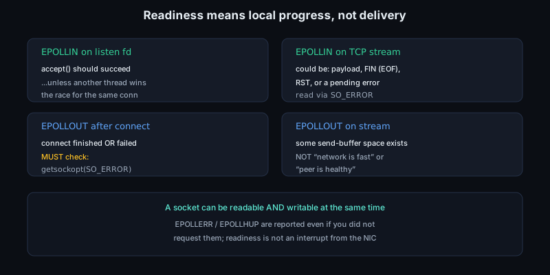
Socket buffers are the first visible backpressure boundary. The receive buffer limits how much data the kernel will queue for a socket before TCP advertises a smaller window or drops UDP datagrams. The send buffer limits how far the application can get ahead of TCP transmission, retransmission, and device scheduling. Autotuning changes these limits based on observed flow behavior, but the accounting is still real memory pressure. Large buffers hide latency and absorb bursts; they also increase worst-case memory use and can let an application build queues in the wrong layer.
The data path underneath those calls is where socket programming meets driver work. On transmit, user bytes cross into the kernel socket send buffer, pass through TCP or UDP, get represented as one or more sk_buff packet objects, get wrapped in IP, are routed to an output device, resolved to a link-layer next hop if needed, and enter the qdisc layer before the driver. The driver maps packet buffers for DMA, posts descriptors to the device transmit ring, and rings a transmit doorbell so the NIC can fetch descriptors and bytes. Offloads may let the kernel hand the NIC a large TCP buffer plus header template, with hardware doing segmentation or checksums.
On receive, the direction reverses. The NIC receives frames, validates what it can, DMAs packet data into host memory, and reports completed descriptors. The driver turns those completions into kernel packet objects, commonly sk_buff structures on Linux. An sk_buff carries pointers to packet data, protocol headers, checksum state, timestamp metadata, device identity, and enough ownership information for the stack to clone, trim, coalesce, or free it without copying the payload unnecessarily. NAPI polling helps process bursts without one interrupt per packet: the interrupt schedules a poll budget, the driver drains receive completions, refills receive rings with fresh buffers, and hands packets upward. If user code does not drain sockets, pressure propagates backward through the receive buffer, protocol queues, NAPI backlog, ring refill, and eventually drops.
Transmit has a similar chain in the other direction. A TCP send can create or extend socket-owned buffers long before the driver has descriptors available. TCP decides when bytes are eligible based on congestion control, receiver window, retransmission state, corking, and pacing. The qdisc layer may queue or shape packets before the driver sees them. The driver then owns a finite transmit ring. If the ring is full, the netdev queue can stop; completions from the NIC later free descriptors and wake the queue. From C code in user space, all of that complexity is compressed into short writes, EAGAIN, SIGPIPE or EPIPE, and occasional latency spikes.
This is why low-level engineers cannot treat sockets as "just an API." Socket buffer sizes affect backpressure into TCP and driver queues. Non-blocking code changes when packets are drained and when receive rings refill. Checksum offload, segmentation offload, timestamping, RSS, busy polling, and zero-copy features all exist because moving data between NIC, kernel, and application is often the dominant cost. A socket is the clean interface; the data path is the machinery that makes it honest at line rate.
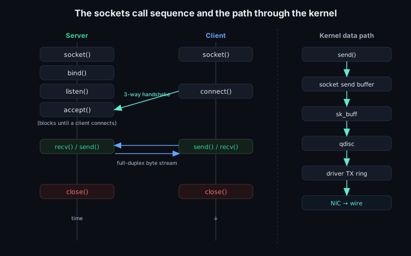
Sources
6.9 Names, ports, and how an app connects
A program rarely starts with an IP address. It starts with a name: www.example.com, api.internal, db01.prod, or something a human can remember and an administrator can move. The network does not forward packets to names, so the first job is translation. DNS is the distributed database that maps names to resource records, including A records for IPv4 addresses and AAAA records for IPv6 addresses. A resolver library in the process, often reached through getaddrinfo, applies local policy and asks a resolver configured by the OS, DHCP, VPN software, or static files. That may mean DNS, /etc/hosts, a name service switch module, search suffixes, or service-name lookup for "https" in /etc/services.
On Linux, the host resolver path is deliberately more than "send a DNS packet". A typical getaddrinfo call enters libc, consults /etc/nsswitch.conf for the hosts database order, may check /etc/hosts, and only then may use DNS servers, search domains, and options from /etc/resolv.conf. Corporate VPN clients, systemd-resolved, nscd, sssd, containers, and network namespaces can all change what "the resolver" means for one process versus another. This is why dig www.example.com and an application's connect path can disagree: dig asks DNS directly unless told otherwise, while getaddrinfo follows the host's name-service policy.
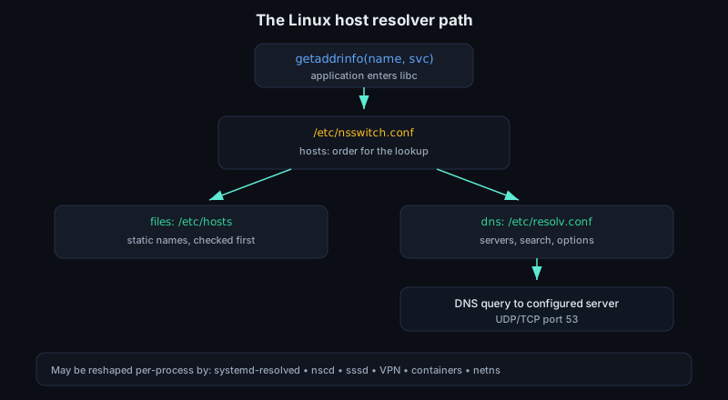
For C code, getaddrinfo is a policy boundary. The caller provides a node name, a service name or numeric port, and optional hints such as AF_UNSPEC, SOCK_STREAM, or IPPROTO_TCP. The result is a linked list of addrinfo entries whose sockaddrs contain an address family and port in network byte order. With AF_UNSPEC, the list may contain both IPv6 and IPv4 addresses. Its order can reflect host address selection policy, source address availability, and local configuration. Correct client code iterates the list, tries candidates until one works, and releases it with freeaddrinfo. Treating the first returned address as permanent state is a common source of brittle failover behavior.
That lookup is itself network traffic when DNS is involved. Traditional DNS queries use UDP port 53, with TCP also defined and used when needed, such as for large responses, zone transfers, or retry after truncation. The fundamental result is the same: the application receives one or more candidate socket addresses. DNS is not a connection mechanism. It is the naming step before the connection step, and it can return multiple answers for load sharing, failover, IPv4/IPv6 preference, or locality.
A DNS message starts with a fixed 12-byte header: an ID, flags, and four 16-bit counts named QDCOUNT, ANCOUNT, NSCOUNT, and ARCOUNT. Those counts describe the question, answer, authority, and additional sections that follow. A resource record has a name, type, class, TTL, data length, and type-specific data. Common types are A for a 32-bit IPv4 address, AAAA for a 128-bit IPv6 address, CNAME for an alias to a canonical name, NS for the name servers authoritative for a zone, MX for mail exchange routing, and SOA for the start-of-authority record that carries zone administration and timing fields. In packet parsers, DNS is hostile to casual string handling: names are length-prefixed labels, messages may use compression pointers, and malformed lengths or pointer loops are a classic bug source in low-level C.
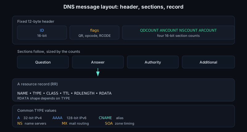
Recursive resolution is a walk through delegation. A stub resolver on the host usually asks a recursive resolver, not the root servers directly. If the recursive resolver has no cached answer, it asks a root server where to find the relevant top-level domain, such as .com; asks a .com authoritative server where to find example.com; then asks an authoritative server for example.com for the requested name and type. The referrals are mostly NS records, with address "glue" records in the additional section when needed to reach the delegated name servers. The client often sees only the final response, but latency, cache state, and failure modes come from this chain.
Transport is part of DNS behavior. Classic UDP DNS had a 512-byte message size limit absent extensions; EDNS0 lets a requester advertise a larger UDP payload size using an OPT pseudo-record, but the path MTU and middleboxes still matter. If a UDP response is too large, the server can set the TC truncation bit and the client retries over TCP port 53; TCP is also used for zone transfers and is required by modern DNS implementations, not just a historical edge case. DNS over TLS uses an encrypted TCP connection, commonly port 853, and DNS over HTTPS carries DNS messages inside HTTPS exchanges. Those protect the stub-to-resolver leg from local observation or tampering, but they do not turn names into routing identifiers: packets still leave the host addressed to a resolver first, then later to the application server.
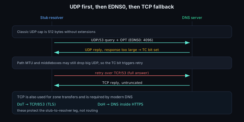
Caching is part of DNS correctness, not just an optimization. Authoritative answers carry a time-to-live, and recursive resolvers cache the data while decrementing that TTL. A host or browser may cache too. The getaddrinfo interface normally does not expose the remaining TTL, so application address caches should honor DNS policy or stay short-lived. Negative answers can be cached too, which matters when a name has just been created or a failed deployment is being rolled back. Low TTLs do not move existing TCP connections; they only affect future resolution. High TTLs reduce query load but can delay traffic shifting after a service migration.
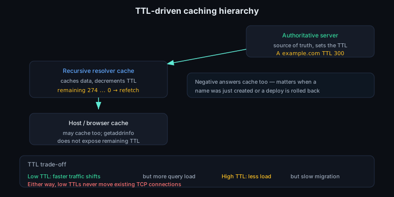
Dual-stack clients add another wrinkle. A resolver may return AAAA and A records, but a usable IPv6 address on the client does not guarantee a working IPv6 path to the server. Happy Eyeballs algorithms avoid making the user wait for a broken family by starting connection attempts to multiple candidate addresses with a small stagger and using the first one that succeeds. In packet captures this can look like extra SYNs, canceled nonblocking connects, or a reset on the losing attempt. For kernel and driver work, it means one logical application connection attempt may briefly create several candidate flows.
The next question is the service. An IP address identifies a host interface; a port identifies a transport-layer service endpoint on that host. The IANA registry divides the 16-bit port space into System Ports 0-1023, User Ports 1024-49151, and Dynamic or Private Ports 49152-65535. System ports include conventional services such as HTTP on TCP 80, HTTPS on TCP 443, and DNS on UDP/TCP 53. User ports are also assignable for registered services. Dynamic ports are not assigned by IANA; they are set aside for local, temporary use.
In normal client/server traffic the server listens on a known destination port, while the client lets the kernel choose a temporary source port. That source port is called an ephemeral port, though operating systems use configurable ranges and selection algorithms. Modern kernels usually choose ephemeral ports with randomness and collision checking. The important property is uniqueness for the protocol and endpoint combination that the kernel must demultiplex. If a browser opens two HTTPS connections from the same laptop to the same remote address and port, the local source ports differ, so the kernel, NIC filters, packet captures, and firewalls can distinguish them. At high connection rates, ephemeral port exhaustion and TCP TIME_WAIT can become real limits, especially when many clients connect from one source address to one destination tuple.
Ephemeral exhaustion is not only a client-host issue. A NAT gateway has to allocate an outside source ip:port for each active translated flow. If thousands of inside clients all open short-lived TCP connections from one public IPv4 address to the same remote ip:port, the NAT can run out of usable source ports for that destination even while CPU and bandwidth look fine. The symptoms can be odd: intermittent connect failures, delayed retries, or resets under bursty load. This is one reason high-performance clients prefer connection reuse, HTTP keep-alive, HTTP/2 multiplexing, or a larger pool of source addresses rather than blindly opening and closing connections at line rate.
For TCP and UDP over IP, the practical identity of a flow is the 4-tuple: source IP address, source port, destination IP address, and destination port, with the transport protocol usually implicit or added as the familiar 5-tuple in firewall and RSS terminology. TCP also has sequence numbers, acknowledgments, windows, timers, and connection state, but incoming segments are first demultiplexed to the right socket by endpoint information. UDP has no connection establishment, but connected UDP sockets and many packet-processing paths still use the same tuple-shaped key for lookup, filtering, hashing, and receive steering. In hardware and drivers this matters immediately: receive-side scaling hashes packet headers so packets from the same flow tend to land on the same queue and CPU. A bug in parsing IPv4 versus IPv6 headers, VLAN tags, fragments, extension headers, tunnels, or TCP/UDP offsets can become a performance bug long before it becomes an obvious correctness bug.
NAT changes the tuple while trying to preserve the conversation. A typical outbound IPv4 NAT rewrites the private source address and often the source port, records a translation table entry, and reverses the mapping for replies. If two inside hosts use the same source port to reach the same server, the NAT must allocate distinct outside tuples. Inside and outside captures will not match byte for byte, and TCP or UDP checksums must be updated after address or port translation. Firewalls and connection trackers build similar state, sometimes without rewriting. Their idea of "established" depends on seeing the expected direction, flags, and tuple transitions.
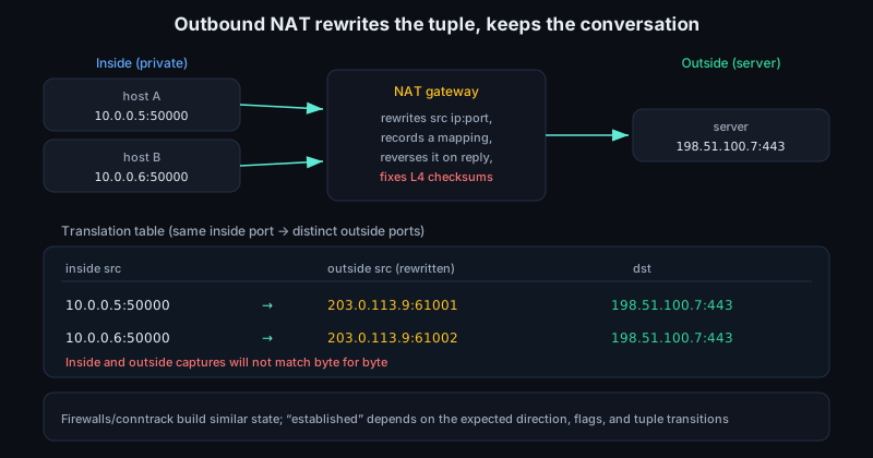
Consider an application making https://www.example.com/index.html. The URL gives a scheme, a host name, and a path. The scheme implies a default service: HTTPS means TCP port 443 unless the URL says otherwise. The application asks the host resolver for addresses for www.example.com; local policy may answer from /etc/hosts, a cache, or DNS. If DNS is used, the recursive resolver may walk root to TLD to authoritative servers, cache the result according to TTLs, and return AAAA, A, or a CNAME chain ending in address records. The client chooses a candidate, creates a TCP socket, and calls connect.
At that point the kernel assigns a local address and ephemeral source port, perhaps 192.0.2.10:53024, and records the peer, perhaps 93.184.216.34:443. It emits a TCP SYN from source port 53024 to destination port 443, inside an IP packet from 192.0.2.10 to 93.184.216.34, inside an Ethernet frame for the next hop. The destination MAC address is only for the local link; the IP addresses and TCP ports are the end-to-end identifiers visible across routed hops, subject to NAT or tunneling.
The server receives the SYN on its listening socket for port 443. The listening socket is not yet the data connection; it is a rendezvous point. After the TCP three-way handshake, the server has a distinct established socket keyed by the client and server addresses and ports. Thousands of clients can connect to the same server IP and port because their source addresses and source ports differ. Once TCP is established, TLS negotiation begins, then the HTTP request bytes are carried as TCP payload. In order, the user typed a name, the host converted it to candidate addresses, the kernel created a tuple and handshake, TLS authenticated the name, and HTTP sent the request. DNS has disappeared from the packet stream unless the application performs more lookups; the path now sees addresses, ports, and protocol headers.
TLS brings the name back at the application security layer. With HTTPS, the client normally sends the intended host name in the TLS Server Name Indication extension, so one IP address and one TCP port can serve different certificates and virtual hosts. The certificate is validated against the host name, not against the raw IP address that connect used. SNI is visible in the ClientHello in ordinary TLS deployments, while HTTP is encrypted after the handshake. A wrong SNI value can produce a certificate error even though DNS, TCP, and the port number are correct.
For low-level engineers, this division is practical. Name resolution explains why a connection may never produce a SYN. Port selection explains why two captures of the same application do not use the same client-side port. The 4-tuple explains socket lookup, NAT tables, firewall state, RSS hash inputs, and many NIC flow-steering rules. When debugging a driver or packet path, the question is rarely just "did a packet arrive?" It is "which flow did this packet belong to, which queue received it, and which socket should consume it?"
A useful debugging order is:
- Check what
getaddrinforeturned: family, numeric address, port, and ordering. - Check whether the application uses serial connects, nonblocking connects, or Happy Eyeballs. Multiple
SYNs may belong to one user-visible operation. - Check the local tuple with
ss,netstat, or a host capture. Verify the source address as well as the ephemeral port. - Check both sides of a firewall or NAT when possible. If the tuple changes, follow the translated tuple.
- For TLS failures, inspect the ClientHello SNI and the certificate name.
- For UDP, remember there is no handshake. Use socket state, logs, ICMP errors, conntrack state, and bidirectional captures.
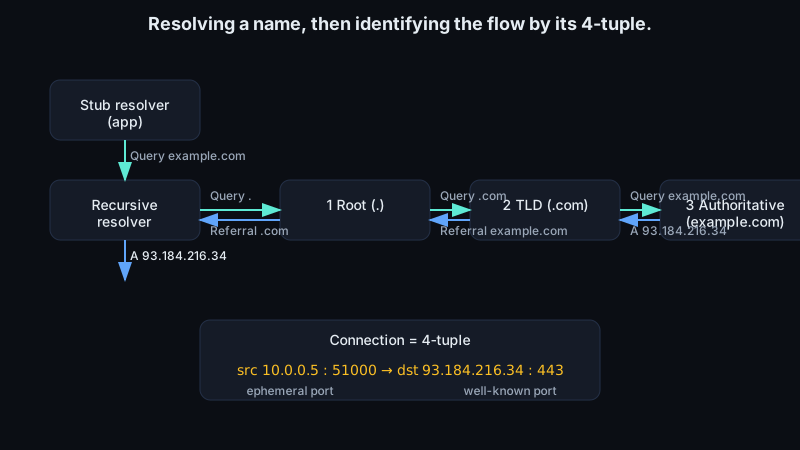
Sources
- RFC 1035: Domain Names - Implementation and Specification
- RFC 2308: Negative Caching of DNS Queries
- RFC 6335: Service Name and Transport Protocol Port Number Procedures
- IANA Service Name and Transport Protocol Port Number Registry
- RFC 9293: Transmission Control Protocol
- RFC 6724: Default Address Selection for Internet Protocol Version 6
- RFC 8305: Happy Eyeballs Version 2
- RFC 6066: Transport Layer Security Extensions
- RFC 6891: Extension Mechanisms for DNS (EDNS(0))
- RFC 7766: DNS Transport over TCP - Implementation Requirements
- getaddrinfo(3) - Linux manual page
6.10 Tools of the trade
Network tools let you compare three views of the same event: what the application thinks it did, what the kernel believes is configured, and what appeared on the wire. Low-level networking work often lives in the gap between those views. A socket write can succeed while packets are dropped by routing, neighbor resolution, checksum offload, a driver bug, or the peer. Good debugging starts by locating the layer where reality stops matching the model.
tcpdump is the simplest way to ask, "which packets crossed this interface?" It uses the packet capture path, normally through libpcap, to receive copies of frames selected by a capture filter. A typical first capture is tcpdump -i eth0 -nn -s 0 -w out.pcap. The -i chooses the interface, -nn avoids DNS and service-name lookups, -s 0 captures the full packet, and -w stores it for later analysis. Capture filters such as host 192.0.2.10, tcp port 443, or arp are applied before packets are saved, reducing volume and loss. A wrong capture filter can remove the evidence you needed.
On Linux, the usual libpcap path is an AF_PACKET socket bound to an interface. With SOCK_RAW, packet data includes the link-layer header; with ETH_P_ALL, the socket can receive every Ethernet protocol type. The filter language used by tcpdump is compiled into classic BPF instructions and attached to that capture socket, so most unwanted traffic is rejected before userspace copies and pcap writes. A minimal raw capture socket looks like this:
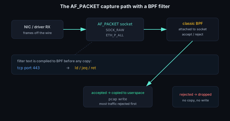
int fd = socket(AF_PACKET, SOCK_RAW, htons(ETH_P_ALL));
That placement matters. AF_PACKET observes packets at the device-driver level, after driver receive processing has created a packet for the kernel and before normal protocol delivery. It is close to the wire, but it is not a passive optical tap. Driver behavior, offloads, qdiscs, virtual devices, and namespace boundaries still shape what the capture path sees.
Make the capture falsifiable. Capture on the interface the kernel route says will be used, not just any, when L2 headers, VLAN tags, or direction matter. Add -e for Ethernet headers and -vvv when TTL, MSS, window scale, ECN, or ICMP detail is useful inline. For bursty traffic, increase the capture buffer with -B and read tcpdump's final dropped-packet summary; a quiet pcap from an overloaded capture path is not proof that packets were absent. On Linux, tcpdump -Q in or -Q out can separate receive from transmit on supporting paths, which helps when a veth, bridge, or qdisc makes the same packet visible more than once.
Wireshark reads the resulting pcap and gives the same bytes a protocol-aware display. A capture filter decides what is recorded; a display filter decides what is shown after recording. tcp port 443 is a capture-filter style expression; tcp.port == 443 is a Wireshark display filter. Wireshark dissectors parse protocol fields, follow conversations, reassemble streams, decode options, and attach expert annotations. Do not treat the decoder as magic. Each expanded field is still derived from bytes in an Ethernet frame, IP packet, TCP segment, or UDP datagram. When Wireshark says "TCP retransmission", it is inferring that from sequence numbers, acknowledgements, timing, and prior packets.
Captures near a modern NIC require caution. Hardware offloads move work out of the CPU path. With transmit checksum offload, a capture taken before the NIC fills the checksum may show a bad checksum even though the frame on the wire is valid. With TCP segmentation offload, the host may hand the NIC a large buffer that later becomes many MTU-sized frames. With receive coalescing, the host may see larger aggregated packets than the link carried. A capture on the sender, a capture on the receiver, and NIC counters may all be telling true but different stories.
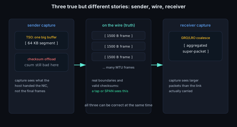
This is a key low-level debugging gotcha: GRO, LRO, TSO, GSO, checksum offload, and RSS mean a host-side capture does not necessarily show true on-wire packet boundaries, checksums, queue choice, or timing. If segment boundaries matter, disable the relevant offloads temporarily with ethtool -K eth0 gro off lro off tso off gso off rx off tx off, or capture outside the host with a tap, switch SPAN port, or NIC hardware timestamping path. Restore the original settings after the experiment; disabling offloads can change CPU cost, pacing, and queue pressure.
Packet timestamps need the same skepticism. A pcap timestamp may come from software when the packet reaches the capture path, from a NIC hardware clock, or from a remote machine with a different clock discipline. NTP or PTP error, interrupt moderation, NAPI polling, GRO, and VM scheduling can move timestamps away from the moment a bit crossed the wire. For latency work, compare clocks before comparing packets. For ordering work, prefer sequence numbers, TCP acknowledgements, ICMP quotations, and monotonic counter deltas over tiny timestamp differences between hosts.
ping asks a narrower question: can an IP packet reach a target and can a reply return? For IPv4 it uses ICMP Echo Request and Echo Reply messages. The output gives round-trip time, loss, and usually the TTL observed in the reply. It does not prove that TCP or UDP to a service will work, because firewalls, routing policy, MTU, port filtering, and application state can differ. It is still a cheap test of addressing, routing, neighbor discovery, and return path. ping -c 3 192.0.2.10 often separates "the service is down" from "the host or route is not reachable."
traceroute asks where forwarding fails or changes. It sends probes with small IP TTL values. Each router that forwards an IPv4 packet decrements TTL; if it reaches zero, the router discards the packet and can return an ICMP Time Exceeded message. By sending probes with TTL 1, then 2, then 3, the tool discovers successive hops. Traditional Unix traceroute often uses UDP probes to high destination ports; many implementations can also use ICMP or TCP probes. The choice matters because networks sometimes treat protocols differently. A TCP SYN traceroute to port 443 may follow a path that a UDP traceroute does not.
Ping and traceroute also expose path-MTU and control-plane limits. ping -M do -s 1472 on IPv4 tests a 1500-byte path when headers are ordinary, but tunnels, VLANs, and IPv6 change the arithmetic. Missing ICMP "fragmentation needed" messages can produce black-hole MTU failures where small packets work and full-size TCP stalls. Traceroute gaps are not always forwarding gaps; routers may rate-limit or suppress ICMP while forwarding data packets normally.
When debugging Linux hosts, ip shows the kernel's network objects. ip link shows interfaces, administrative state, MTU, MAC address, and packet counters. ip addr shows configured IPv4 and IPv6 addresses. ip route get 203.0.113.5 asks the kernel to route one destination, which is often better than reading the whole table and guessing. ip neigh shows ARP and IPv6 neighbor-discovery state: known, stale, failed, or still being resolved. For NIC work, ip -s link show dev eth0 bridges software and hardware symptoms: RX drops, TX errors, carrier state, and MTU mismatches may appear there before an application reports anything useful.
Use the more specific ip forms when the question is specific. ip route get 203.0.113.5 from 192.0.2.20 iif eth0 exercises policy routing, source address choice, reverse-path assumptions, and output device selection for one hypothetical packet. ip neigh show dev eth0 tells you whether the next hop is REACHABLE, STALE, DELAY, PROBE, or FAILED; a stuck TCP SYN-SENT with a FAILED neighbor is not a congestion-control problem. ip -s link show dev eth0 gives portable packet, byte, error, dropped, overrun, carrier, and collision counters from the netdev view.
ss looks from the socket side. Where ip describes interfaces, addresses, routes, and neighbors, ss describes endpoints owned by processes and protocols. ss -ltnp shows listening TCP sockets with numeric addresses and process names when permissions allow. ss -tan shows TCP states such as SYN-SENT, ESTAB, FIN-WAIT-1, and TIME-WAIT. ss -uap is useful for UDP sockets, where there is no connection establishment. With ss -tin, Linux can show TCP details such as congestion-control state, retransmission timer information, RTT estimates, and receive/send queue sizes.
For a live TCP connection, ss -tiepm dst 203.0.113.5 is a compact transport-layer microscope. -t selects TCP, -i asks for internal TCP information, -e adds socket identity, -p maps the socket to a process when permitted, and -m prints socket memory. Read rtt:0.45/0.08 as smoothed RTT and RTT variation in milliseconds, not as application latency. cwnd:10 is the congestion window in MSS-sized segments, so its byte budget is roughly cwnd * mss. ssthresh is the slow-start threshold after congestion response. retrans and the timer field show whether TCP is recovering loss or waiting for retransmission. bytes_acked is cumulative data acknowledged by the peer. A growing Send-Q with flat bytes_acked points somewhere very different from a growing Recv-Q.
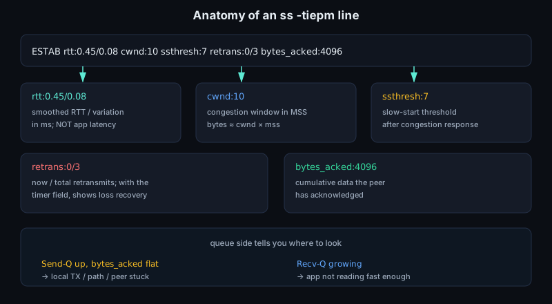
ethtool looks below the socket and interface model. ethtool eth0 checks link mode, speed, duplex, and autonegotiation. ethtool -k eth0 shows offloads such as checksum, TSO, GSO, GRO, LRO, and VLAN acceleration; record these before interpreting a capture. ethtool -S eth0 exposes driver and NIC counters whose names are device-specific but often include ring drops, missed packets, CRC errors, pause frames, descriptor starvation, and queue-level failures. ethtool -i eth0 identifies the driver and firmware, which matters when a symptom matches a known hardware or driver path.
For NIC, driver, and kernel-bypass work, ethtool is not just a link-status command. ethtool -S eth0 is where per-queue RX/TX counters, DMA or descriptor shortages, XDP action counts, checksum errors, and driver-specific drops often appear. ethtool -c eth0 shows interrupt coalescing: high rx-usecs or adaptive moderation can improve throughput but hide microbursts and add tail latency. ethtool -l eth0 shows channel counts; ethtool -g eth0 shows ring sizes, which bound how much burst the driver can absorb before software catches up. ethtool -x eth0 prints the RSS indirection table and hash key. ethtool -T eth0 shows hardware timestamping and PTP clock capabilities.
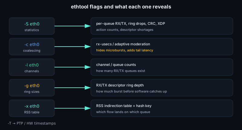
Counters are most useful as deltas. Take a baseline, reproduce the symptom, then read ip -s link, ethtool -S, nstat, /proc/net/snmp, and relevant application counters again. RX errors with no tcpdump packets point toward the NIC, PHY, or driver receive path. TCP retransmits with no interface drops point toward path loss, congestion, reordering, or a peer that is slow to acknowledge. A growing send queue in ss with no transmitted packets points back to routing, neighbor state, qdisc limits, or local policy.
The qdisc is the transmit scheduler between the kernel's packet output path and the driver. tc -s qdisc show dev eth0 reports enqueue, dequeue, drop, overlimit, and backlog state. On real NICs, multiqueue devices may show per-queue qdiscs; on virtual devices, noqueue may be correct. If tcpdump shows an application generating packets but the peer never sees them, qdisc drops, shaping, class filters, and tc actions belong in the same search space as routing and firewall rules.
Namespaces and veth pairs add another visibility problem: each namespace has its own interfaces, routes, neighbors, sockets, qdiscs, and counters. Use ip netns exec ns1 ip route get ..., ip netns exec ns1 ss -tan, and ip netns exec ns1 tcpdump -i eth0 -nn from inside the namespace rather than assuming the host view is enough. For veth debugging, capture on both ends when possible. A packet may leave one namespace, hit a host bridge, qdisc, nftables rule, XDP program, or peer namespace policy before it reaches the socket you care about.
When packets disappear in the fast path, use observability tools at the hook where they can still be seen. perf top -g and perf record -g -a can show whether CPU time is in the driver poll function, GRO, TCP, checksum code, copy paths, or userspace. bpftrace can count tracepoints such as skb frees or measure time in a driver NAPI poll routine. XDP programs run very early in the receive path, before normal skb allocation in the native driver case, so an XDP drop or redirect can make tcpdump on the host look empty. Check ip link show, bpftool prog show, and driver ethtool -S counters for XDP pass, drop, redirect, and abort statistics when exposed.
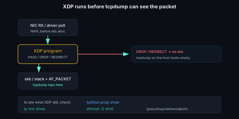
The useful habit is to combine tools in a small chain and let the symptom choose the next question. If a client cannot connect, use ip route get to verify the egress interface and next hop, ip neigh to see whether L2 resolution is working, ping or traceroute to test reachability and path behavior, ss to see whether the socket is listening or stuck in a TCP state, and tcpdump to confirm whether SYNs, ARP requests, ICMP errors, or replies are present. If bytes leave the application but not the host, inspect sockets, policy, qdisc, and NIC counters. If bytes leave the host but not the peer, inspect the path, MTU, offloads, and intermediate drops. If replies reach the host but not the process, inspect demultiplexing, firewall state, namespaces, and receive queues. In low-level work, that chain prevents blaming the wrong layer.
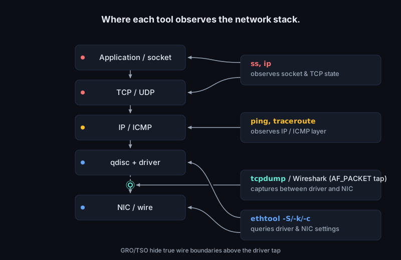
Sources