🔌 Buses, Devices & DMA
How the CPU talks to hardware: MMIO and port I/O, PCIe topology and config space, TLPs, device interrupts, DMA and bus mastering, the IOMMU, and descriptor rings.
5.1 Talking to hardware
A CPU is very good at executing instructions and reading and writing memory. Left alone, though, it is trapped inside that memory model. The useful machine has other actors: a NIC receiving frames from the wire, an SSD completing reads, a GPU consuming command buffers, a timer expiring while the current thread is elsewhere. The basic systems question is therefore simple and deep: how does software talk to a device, how does the device move bytes without turning the CPU into a copy engine, and how does the device get attention when something happens asynchronously?
Two needs keep reappearing. Control is small and explicit: the driver writes a register to enable a queue, reads a status bit, clears an error, arms an interrupt, or rings a doorbell. These operations are usually measured in words, not packets or pages. They form the control plane between CPU and device. Data is bulk movement: packet payloads, disk blocks, command buffers, completion records. If the CPU copied every byte through loads and stores, a fast device would spend the processor's cache bandwidth and cycles just moving data from one place to another.
Modern I/O is built by separating those two jobs. The CPU uses register access, most commonly MMIO today and historically also port I/O on x86, to configure and steer the device. The device uses interrupts to say, "look at me now," without requiring the CPU to poll constantly. For the heavy traffic, the device performs DMA: it becomes a bus master and issues memory reads or writes itself, using addresses and permissions prepared by the operating system.
That all rides on an interconnect. In contemporary servers and workstations, the main one is PCI Express, whose topology, configuration space, BARs, and packet format give software a discoverable way to find devices and map their resources. PCIe is not just "a slot"; it is the transport over which register reads, register writes, DMA reads, DMA writes, and interrupt messages become transactions.
For NIC and driver work, this is not academic. A high-rate NIC cannot afford a CPU copy per packet, and it cannot afford an interrupt per packet either. The usual shape is a shared queue: the driver allocates DMA-capable memory, fills descriptor rings saying where buffers live, uses an MMIO doorbell to notify the NIC, and later receives completions by polling, interrupts, or a moderated mixture of both. An IOMMU can sit between device and memory so "DMA to address X" means only what the kernel allowed it to mean, not arbitrary physical memory access.
The rest of this chapter names each piece precisely and then connects them into the familiar driver pattern: discover the device, map registers, configure queues, give the device safe memory to touch, start DMA, and handle completion without wasting the CPU.
Sources
5.2 MMIO vs port I/O
The CPU does not have a magical "talk to device" operation. It can execute loads and stores, and on x86 it also has a separate family of I/O instructions. Device control and status registers must therefore be reachable through one of those mechanisms. Historically there were two answers: put registers in a separate I/O address space, or map them into the same physical address space as RAM.
Port I/O is the separate-address-space model. On x86, the I/O port space is 16 bits wide: 0x0000 through 0xffff, or 64 KiB of ports. The CPU accesses it with privileged IN and OUT instructions, plus the string forms INS and OUTS for repeated transfers. Linux exposes the familiar byte/word/long helpers as inb(), outb(), inw(), outw(), inl(), and outl(); user-space programs that use the glibc <sys/io.h> versions must first obtain permission with ioperm() or iopl().
#include <sys/io.h>

outb(0x01, 0x3f8);
status = inb(0x3f8 + 5);
Port I/O survives for legacy devices and some early x86 PCI configuration mechanisms, but it is x86 baggage: privileged, narrow, limited to 64 KiB, and naturally one explicit I/O instruction at a time. Most other mainstream ISAs, including ARM and RISC-V, do not have this separate I/O space architecturally; devices are reached through memory-mapped I/O.
MMIO folds device registers into the physical address space. A load or store to a certain physical address is not sent to DRAM; the memory system, chipset, or root complex routes it to the device. Modern PCIe devices expose register windows that get mapped into physical address space, usually through BARs, covered next. Once mapped, a register looks addressable, but it is not normal memory.
In a Linux driver, the physical MMIO window is mapped into the kernel's virtual address space with ioremap(), ioremap_uc(), or ioremap_wc(). The returned pointer is an __iomem pointer, and drivers use accessors such as readb(), readw(), readl(), writeb(), writew(), and writel() rather than dereferencing it as a C pointer.
void __iomem *regs = ioremap(base, size);

writel(CTRL_ENABLE, regs + CTRL);
state = readl(regs + STATUS);
MMIO won because it scales with the machine. It uses normal translation and protection, benefits from a huge 64-bit physical address space, needs no special instruction family, supports natural access widths and burst-like traffic, and is the uniform model across PCIe and non-x86 systems.
The subtle part is that MMIO addresses must not be treated like cacheable RAM. If a CPU cached a status register in WB write-back memory, it might keep returning the old value while the device reports completion. If it combined or reordered control-register stores, the device might see commands in the wrong order. x86 controls effective memory type with MTRRs and the PAT; Linux exposes the relevant choices through mapping APIs.
For control and status registers, the conservative type is UC: uncacheable. A UC MMIO load really goes to the device, and a UC store is not absorbed into a CPU cache or combined with its neighbors. This is the correct default where reads observe hardware state and writes have side effects.
WC, write-combining, is different. Stores may sit in a write-combine buffer, merge with adjacent stores, and reach the bus later as a larger burst. That is excellent for a framebuffer or for high-throughput transmit paths where software streams a block toward the device with fewer transactions. It is not a drop-in replacement for UC: WC writes can be delayed and reordered, so the driver must define when the device may observe them. The descriptor-ring and doorbell pattern is treated later; for now, ioremap_wc() buys throughput by relaxing timing.
Device registers are also the canonical low-level use of volatile. A status bit can change without a C write, and a register write can command hardware even if the value appears redundant to the optimizer. A poll loop must really reload the register each time:
while (!(readl(regs + STATUS) & STATUS_READY))
        cpu_relax();
The caveat from the C and memory-model chapters still applies: volatile is a compiler constraint, not a synchronization primitive. It prevents caching, deletion, or reordering of volatile accesses relative to each other; it is not atomic or a CPU memory barrier. It does not order a normal-memory write to a DMA descriptor before an MMIO doorbell write.
That is why Linux drivers use the accessor API instead of hand-rolled volatile pointers. The accessors encode architecture-specific volatile behavior, type handling, endian conventions, and ordering rules. Ordered writel() provides stronger ordering than writel_relaxed(); if you choose the relaxed form, you take responsibility for the missing ordering.
Barriers enter when register accesses must be ordered against ordinary memory or other device-visible operations. wmb(), rmb(), and mb() express write, read, and full ordering constraints. Even if a control register is mapped UC, that alone does not flush a WC buffer or prove that a previous normal-memory store has become visible to a bus-mastering device before the register write arrives. The exact descriptor and doorbell rules belong to the later DMA sections, but the reason they exist starts here.
Sources
5.3 PCI/PCIe topology
The original PCI family was a bus in the old electrical sense: many devices attached to one shared set of wires. Conventional PCI used a parallel, multidrop bus, so each device saw the same wires and only one bus master could drive a transaction at a time. The familiar desktop form was 32-bit at 33 MHz, which works out to about 133 MB/s of peak bandwidth for the whole bus, not for each slot. PCI-X pushed the same basic idea harder, including 133 MHz operation in PCI-X 1.0, but devices still contended for a shared electrical resource.
That shape hit both physics and system-design limits. A parallel bus must sample a whole word at once, so clock skew and trace-length mismatch get harder as frequency rises. More connectors and devices add electrical loading. Because the bus is shared, one slow or heavily loaded segment can constrain the whole segment, and all devices divide the same bandwidth. That is a poor fit once storage, graphics, and network adapters all want sustained throughput.
PCI Express changed the topology instead of merely widening or clocking the old bus faster. A PCIe connection is a link: a dedicated, point-to-point, full-duplex serial connection between two PCIe ports. A link is built from one or more lanes. Each lane has one differential pair for transmit and one differential pair for receive, so both directions can make progress at the same time. Links may negotiate widths such as x1, x4, x8, or x16; the width is the number of lanes bonded together. Unlike old PCI, that bandwidth belongs to that link. A x8 NIC is not sharing those eight lanes with a neighboring endpoint just because both devices are in the same machine.
Serial links also change the clocking problem. PCIe uses SerDes, short for serializer/deserializer, to turn internal parallel data into a high-speed serial stream and recover it at the other end. Clock information is embedded in the stream rather than distributed as a shared bus clock. The generations raised transfer rate from 2.5 GT/s in PCIe 1.x, to 5.0 GT/s in PCIe 2.x, 8.0 GT/s in PCIe 3.0, 16.0 GT/s in PCIe 4.0, and 32.0 GT/s in PCIe 5.0. PCIe 1.x and 2.x use 8b/10b encoding; PCIe 3.0 moved to 128b/130b, reducing encoding overhead. The result is a packetized, layered, switched fabric that remains software-compatible with PCI's configuration model even though the electrical design is completely different.
The fabric is normally a tree. At the top is the root complex, the host-side PCIe logic that connects the CPU and memory subsystem to the PCIe hierarchy. It may live in the CPU package, in a chipset or I/O die, but its role is the same: it is the host's entrance into the PCIe fabric. When CPU code touches an MMIO address belonging to a device, the host side turns that operation into PCIe traffic. The ports facing away from the root complex are root ports; each root port is a downstream port that begins a PCIe hierarchy below it.
A root port can connect directly to an endpoint, but real systems often need fan-out. That is the job of a switch. A PCIe switch has one upstream port, toward the root complex, and multiple downstream ports, toward devices or lower switches. Electrically, each port-to-port connection is still its own point-to-point link, with its own negotiated generation and lane width. Logically, the switch forwards packets between ports, so several endpoints can sit below one root port without being placed on a shared parallel bus.
The software model deliberately preserves the older PCI bridge view. A bridge connects one PCI bus segment to another; in PCIe, root ports and switch downstream ports appear to software as PCI-to-PCI bridges. Internally, a switch is modeled as virtual PCI-to-PCI bridges behind its upstream side, one for each downstream port. This is why operating systems still describe a PCIe machine as a hierarchy of buses even though the hardware is serial and switched. The tree determines which devices are close to the root, which devices share an upstream link, and which paths pass through switches.
The leaves of the tree are endpoints. An endpoint is the actual device function the system will drive: a network adapter, an NVMe controller, a GPU, a capture card, or an FPGA accelerator. A Solarflare or AMD Ethernet adapter is such a leaf. It has an upstream PCIe link toward the root complex and exposes a device interface that software can discover; later sections will explain configuration space, interrupts, and DMA-capable queues.
For low-level networking work, topology is not trivia. A high-bandwidth NIC needs enough PCIe bandwidth and should usually sit on a wide, new-enough link close to the root complex. A 100 Gb/s class adapter behind a narrow or older-generation link can be limited by PCIe before the wire protocol is the bottleneck. Two busy devices behind the same switch may each have a fast endpoint link yet still contend for the switch's upstream link. On Linux, lspci -t gives a compact view of this tree. Before blaming a driver or packet path, first know where the card sits.

Sources
5.4 Config space, BDF, and BARs
PCI and PCIe devices are not discovered by probing their MMIO registers blindly. Each function exposes standardized configuration space that firmware and the OS can read before a driver knows anything device-specific. Classic PCI defines 256 bytes of configuration space per function. PCIe keeps that compatible first 256 bytes and extends the per-function space to 4096 bytes, mainly for PCIe extended capabilities above 0x100.
The address of a function is its BDF: bus:device.function. The fields are fixed-width: an 8-bit bus number, a 5-bit device number, and a 3-bit function number. That gives 256 buses, 32 device numbers per bus, and up to 8 functions per device. Linux usually prints this with a PCI domain in front, for example 0000:03:00.0; the 03:00.0 part is the BDF. For a NIC, lspci -vv -s 03:00.0 shows identity, class, enabled features, BARs, interrupts, and capabilities.
The first bytes are deliberately boring and universal. For a Type 0 header, used by ordinary endpoints rather than bridges, the important fields include:
Vendor IDat0x00andDevice IDat0x02; a read returning0xffffforVendor IDmeans no function responded.Commandat0x04andStatusat0x06;Commandenables responses to I/O space, memory space, and bus mastering.Revision IDat0x08, programming interface at0x09, subclass at0x0a, and baseClass Codeat0x0b.Header Typeat0x0e; low bits select the header layout, and bit7says whether the device is multifunction.- BARs at
0x10,0x14,0x18,0x1c,0x20, and0x24: six32-bit Base Address Register slots for a Type0function.
Those offsets are why a driver can be matched before it maps any device registers. The PCI core reads Vendor ID, Device ID, and often class fields, matches them against driver tables, then calls the driver's probe routine. A NIC driver does not guess a register address; it asks the kernel for the resource described by a BAR, maps that resource, and only then touches device-specific registers.
On legacy x86 PCI, configuration mechanism 1 uses port I/O: software writes an encoded address to 0xcf8 (CONFIG_ADDRESS) and reads or writes data through 0xcfc (CONFIG_DATA). The encoding includes enable bit 31, then bus, device, function, and register offset. This reaches the legacy 256-byte configuration area.
PCIe defines ECAM, the Enhanced Configuration Access Mechanism. ECAM maps configuration space into an MMIO region described to the OS by platform firmware, commonly through ACPI MCFG on x86. Conceptually, the byte address is:
ecam_base + (bus << 20) + (device << 15) + (function << 12) + offset
Each function gets 4096 bytes, so function selection starts at bit 12; eight functions and thirty-two devices occupy the next 8 bits; the bus starts at bit 20. Config reads and writes still become PCIe configuration transactions, but the transaction details belong to the next layer down.
Enumeration is a tree walk over the existing hierarchy. Firmware may do it before boot; the OS may validate, extend, or redo it. For each candidate BDF, read Vendor ID; if it is 0xffff, nothing is present. If function 0 exists, read Header Type; if multifunction is set, scan functions 1 through 7. When a bridge is found, software assigns or reads secondary/subordinate bus numbers and recursively scans the bus behind it. The result is a set of discovered functions and resource requests.
BARs express those resource requests. A BAR identifies the address space the function needs, and after assignment it holds the base address the device will decode. Bit 0 distinguishes memory BARs from I/O-space BARs. For a memory BAR, bits 2:1 encode address type, including 64-bit memory BARs, and bit 3 is the prefetchable attribute. The actual base is aligned, so the low attribute bits are not address bits. For an I/O BAR, the base is taken from the remaining aligned bits.
Sizing a BAR is a standardized destructive-looking but controlled probe:
old = read_config32(bar);
write_config32(bar, 0xffffffff);
mask = read_config32(bar);
write_config32(bar, old);
size = ~(mask & address_bits) + 1;
For a memory BAR, address_bits masks off the low attribute bits, normally keeping bits 31:4 for a 32-bit BAR. For an I/O BAR, it keeps bits 31:2. A 64-bit memory BAR consumes two adjacent BAR slots: the low dword contains the type bits and low address bits, and the next BAR contains the upper 32 address bits. Software must treat the pair as one BAR, both when sizing and when assigning.
Assignment is the other half of enumeration. Firmware or the OS collects BAR sizes, chooses aligned holes in CPU physical address space or I/O port space, writes the bases into the BARs, programs bridge windows, and then sets Command.Memory, Command.IO, and eventually Command.Bus Master as appropriate. From the driver's point of view, the device is now reachable: the NIC's register BAR has a real host physical address, the bridge path forwards it, and the driver can map it.
Sources
5.5 PCIe transactions: TLPs
PCIe looks like a bus to software, but on the wire it is a packet-switched serial network. A core or chipset does not toggle a shared address bus and wait for every card to observe it. Each hop sends framed packets over a point-to-point link, and switches forward them using header fields. This is why PCIe scales to many lanes and devices while preserving the programming model that earlier sections described.
The protocol is split into three layers. The Transaction Layer is closest to software-visible intent: read this address, write these bytes, access configuration space, send a message, return completion data. It creates and consumes Transaction Layer Packets, or TLPs, and applies ordering rules. The Data Link Layer makes a single hop reliable with sequence numbers, link CRC checking, acknowledgements, retries, and Data Link Layer Packets, or DLLPs, for management such as flow-control updates. The Physical Layer handles link training, lane bonding, equalization, scrambling, signaling, and the bits on lanes.
The important unit for driver work is the TLP. Its header is either 3 DWORDs or 4 DWORDs, where a DWORD is 32 bits, so the base header is 12 or 16 bytes. A TLP may also carry a data payload. The first header word contains Fmt and Type; together they identify the packet, whether it has data, and whether the header is 3DW or 4DW. Other fields include traffic class, attributes, length in DWORDs, requester identity, tags used to match completions to requests, byte enables, addresses, and completion status fields for responses.
struct tlp_shape {
    u32 header[3_or_4];   /* Fmt/Type, length, IDs/tag, address or status */
    u32 payload[n];       /* present for writes and completions-with-data */
};
Routing is part of the header design. Address-routed TLPs name an address in memory or I/O space; memory and I/O reads and writes use this form. For memory requests, 3DW carries a 32-bit address and 4DW carries a 64-bit address. ID-routed TLPs name a requester or completer by PCIe ID, the familiar bus/device/function identity. Configuration transactions and completions are routed this way. Implicit-routed TLPs are mostly messages whose direction or destination is inherent in the message type, such as upstream toward the root complex or broadcast downstream. A C driver does not build these headers; an MMIO access or config-space helper causes the host bridge and PCIe fabric to do it. But the packet model explains the latency and ordering you observe.
PCIe transactions fall into three practical classes. Posted requests do not get a completion. The classic example is a memory write, MWr; message TLPs are also posted. Once accepted into the fabric, the requester can move on, subject to ordering rules and available credits. This is why MMIO writes are the usual way to ring a NIC doorbell: the CPU can issue a store without waiting for the device to say "done."
Non-posted requests require a completion. Memory reads, MRd, are non-posted. So are configuration reads and writes, and legacy I/O reads and writes. The requester sends a request, the completer sends back a Completion TLP, and the requester cannot know the result until that completion returns. If data is returned, the response is CplD; if only status is returned, it is Cpl. This is why an MMIO read from a device register is expensive: it is a request packet traveling to the device and a completion packet traveling back, often across a root complex, switches, and the endpoint.
Completions are their own traffic class. They are not optional acknowledgements for posted writes; they are required responses to non-posted work. The requester uses a tag in the original request so returning completions can be matched to outstanding operations. Hardware can have multiple reads in flight, bounded by tags, ordering rules, completion buffer space, and fabric flow control. A low-level driver sees the consequence indirectly: reads serialize control paths unless the architecture batches or avoids them.
PCIe flow control is credit-based and hop-by-hop. A receiver advertises buffer space for each virtual channel, most commonly VC0, and the sender must have enough credits before transmitting onto that link. Accounting is split into six credit types: posted headers PH, posted data PD, non-posted headers NPH, non-posted data NPD, completion headers CPLH, and completion data CPLD. Header credits count TLP headers; data credits count payload buffer space. As the receiver frees buffers, it sends UpdateFC DLLPs to raise the sender's usable credit limit.
This mechanism is why "posted" does not mean "infinite." MMIO writes can run quickly because they do not wait for completions, but they can still stall when posted credits run out on some hop. A memory read is costlier because the requester needs non-posted request credit and must be prepared to receive the completion. In NIC work, this distinction is everywhere: write doorbells when you can, avoid register polling in hot paths, and remember that the PCIe fabric is a finite packet network, not a magic wire attached directly to the device.

Sources
5.6 Device interrupts: INTx, MSI, MSI-X
A device interrupts because something happened that software would otherwise keep asking about. A NIC receives a packet, completes a transmit, detects a link event, or reports an error. The alternative is polling: repeatedly read a status register until a bit changes. Polling is predictable when work is constant, but burns cycles and bus bandwidth when idle. Interrupts invert the flow: the device says "service me", the CPU vectors into a handler, and the driver inspects device state. The trade-off is simple: interrupts save idle work; polling avoids interrupt entry cost under load.
Legacy INTx is the old PCI pin model. A conventional PCI slot exposes four interrupt pins: INTA#, INTB#, INTC#, and INTD#. They are active-low, level-triggered signals. "Level-triggered" means the interrupt remains asserted until the device condition is cleared, avoiding a lost edge while software is busy. "Shared" means multiple devices can be wired to the same system IRQ line, effectively wire-ORed. When that IRQ fires, the kernel cannot know from the line alone which device asked for service.
So an INTx handler must first interrogate its own device:
status = readl(dev->bar + STATUS);
if (!(status & INTR_PENDING))
    return IRQ_NONE;
Returning IRQ_NONE is normal for a shared interrupt. It is how the OS demultiplexes the line. The real owner then clears the condition holding the level active; otherwise the interrupt immediately retriggers. This is robust, but scales poorly: a shared IRQ may call several handlers, each doing device register reads, and one level-triggered line is a bad shape for hardware with many independent queues.
PCI Express removed the shared parallel bus and physical sideband interrupt pins, but preserved PCI compatibility. PCIe represents legacy INTx with in-band Assert_INTx and Deassert_INTx messages. Conceptually the endpoint is still raising and lowering INTA# through INTD#; physically it sends PCIe messages. That path is useful for boot and old drivers, but it keeps the old semantics: shared, level-triggered, slow to demux, and one-dimensional.
MSI replaces the pin with a write. The operating system programs the device's MSI capability in PCI config space with a Message Address and Message Data. When the device wants to interrupt, it writes the data value to that address. On x86, the destination is in the local-APIC interrupt message address space, based around 0xFEE00000; the data payload contains the interrupt vector and delivery attributes. On PCIe, the interrupt is just a posted memory-write TLP aimed at the interrupt controller path.
That has two important effects. First, an MSI is not ambiguous like a shared pin: the OS allocated that vector to that device function. The driver still reads device status, but to learn what completed, not to prove IRQ ownership. Second, because the interrupt is itself a memory write, it participates in PCI/PCIe ordering. If the device writes result data to host memory and then writes the MSI, the earlier writes must be visible first. That closes the classic race where a pin interrupt arrives before the data it announces.
Plain MSI is much better than INTx, but still compact. MSI can provide up to 32 vectors for one function, selected as a power-of-two contiguous block. Those vectors share one programmed message address, with message data varying by vector. That is awkward for a large NIC that wants independent routing for many receive and transmit queues.
MSI-X is the scalable form. Instead of one small MSI register set, the device exposes an MSI-X Table in one of its BARs. Each entry contains its own Message Address, Message Data, and per-vector mask bit. The capability also points to a Pending Bit Array (PBA), where the device can record interrupts that became pending while masked. MSI-X supports up to 2048 vectors per function, and because each entry has independent address and data fields, software can target different vectors at different CPUs.
Masking exists at several levels. A driver or interrupt core may mask a vector while changing affinity, tearing down a queue, or preventing re-entry around a sensitive transition. With MSI-X, the per-entry mask bit makes that precise; with INTx, masking is coarser. Either way, the top-level handler should be short: record the event, acknowledge or mask what must be handled immediately, and hand heavier work to deferred interrupt machinery. Later sections connect that to descriptor rings, queue draining, and interrupt moderation.
The reason this matters in a NIC interview is multi-queue scaling. A modern adapter has many RX queues and many TX queues. RSS steers flows across RX queues, and the driver maps those queues onto CPUs. With MSI-X, queue 17 can have vector 17, targeted at CPU 17, with IRQ affinity keeping that interrupt on the same core that owns the queue. That core drains its own completions, touches cache-hot queue state, and avoids bouncing locks or cache lines through another CPU just to discover that work arrived. MSI-X turns interrupts from one shared alarm bell into per-queue, per-core signals, which is what makes multi-queue throughput and low jitter plausible.
Sources
5.7 DMA and bus mastering
DMA exists because the CPU is the wrong engine for bulk movement between an I/O device and memory. If a NIC receives a 1500-byte Ethernet frame, nothing useful is gained by interrupting the CPU for every word and copying data out of a device register. The useful work is deciding where the packet should go, updating protocol state, and waking the right consumer. The byte movement should be done by hardware. Direct memory access lets the device read or write host memory without the CPU executing a load/store loop for the payload.
On PCIe, a capable endpoint does this by becoming a requester on the fabric. After software has enabled the function and set the Bus Master Enable bit in the PCI command register, the device may initiate transactions of its own. For DMA, those transactions are ordinary PCIe memory transactions: a transmit path may issue Memory Read requests to fetch packet data from host memory; a receive path may issue Memory Write requests to place packet data into host buffers. The CPU is still orchestrating the operation, but it is no longer in the data path for each cache line.
The first trap is the word "address". A C pointer is a CPU virtual address. A CPU physical address is the address after CPU page-table translation. A device doing DMA uses a DMA address, often called a bus address. On simple systems those may be numerically the same as CPU physical addresses; on many real systems they are not, because host bridges or an IOMMU may translate what the device puts on the bus. A Linux driver therefore does not hand a device a void *. It asks the DMA API for a dma_addr_t, and it programs that value into the device.
Linux exposes two main styles of DMA mapping. Coherent mappings are for memory simultaneously shared by the CPU and device, commonly descriptor areas or other control structures. dma_alloc_coherent(dev, size, &dma, gfp) returns a CPU-accessible virtual pointer and a dma_addr_t suitable for the device. Coherent means the CPU and device do not need explicit cache maintenance to observe each other's writes to that memory. It does not mean ordering is magic: if the CPU writes several fields and then tells the device to look, the driver must still order the writes before the notification.
Streaming mappings are for buffers mapped for a particular transfer or series of transfers: packet payloads, disk blocks, crypto input and output. A driver allocates ordinary DMA-capable memory, maps it with dma_map_single() or dma_map_page(), gives the returned dma_addr_t to the device, and later tears the mapping down with dma_unmap_single() or dma_unmap_page(). The mapping direction is part of the contract:
DMA_TO_DEVICE: the CPU has produced data, and the device will read it.DMA_FROM_DEVICE: the device will write data, and the CPU will consume it later.DMA_BIDIRECTIONAL: both sides may read and write during the mapping.
The direction is not decoration. It tells the DMA layer what cache maintenance and mapping permissions are needed. On a coherent x86 server it may compile down to very little. On a non-coherent architecture it may flush dirty CPU cache lines before a device read, invalidate CPU cache lines before a device write is consumed, or perform operations that the driver must not open-code. A receive buffer for a NIC is normally mapped DMA_FROM_DEVICE; a transmit packet is normally mapped DMA_TO_DEVICE.
For a one-shot streaming transfer, the lifetime is simple:
dma = dma_map_single(dev, buf, len, DMA_TO_DEVICE);
if (dma_mapping_error(dev, dma))
        return -EIO;

/* program descriptor with dma */
...
dma_unmap_single(dev, dma, len, DMA_TO_DEVICE);
If the CPU and device take turns accessing the same streaming mapping before it is unmapped, the driver must synchronize ownership. After the device has written a buffer and before the CPU reads it, use dma_sync_single_for_cpu(). After the CPU has modified the buffer and before giving it back to the device, use dma_sync_single_for_device(). The same pattern exists for scatter-gather mappings. These calls are especially important on non-coherent platforms, but portable drivers use the API rather than assuming a cache model.
DMA correctness also depends on ordering. A common transmit path writes packet metadata into memory, stores the DMA address and length into a descriptor, marks the descriptor available to the device, and then writes an MMIO doorbell register. The doorbell is merely a notification; it must not reach the device before the memory writes it points at are visible. Otherwise the NIC may fetch an old descriptor, a half-written descriptor, or payload contents still sitting in a CPU store buffer.
In Linux this is expressed with the appropriate DMA or write barrier before the device is notified. For coherent descriptor memory, dma_wmb() is the usual primitive for ordering descriptor writes observed by a DMA-capable device. In code using relaxed MMIO accessors, an explicit barrier such as wmb() may be needed before the relaxed doorbell write; non-relaxed accessors such as writel() include ordering guarantees defined by the kernel I/O accessor rules. The invariant is: publish memory first, ring the doorbell second.
PCIe has its own transaction ordering rules, but a driver cannot rely on the bus to repair a CPU-side ordering bug. PCIe can order transactions that have actually been issued in a constrained relationship; it cannot force the CPU to write a descriptor to memory before software performs an MMIO store. The driver must create that happens-before edge. This is why DMA bugs often look impossible when staring only at the device: the device did exactly what it was told, but it was told too early.
The practical model is: allocate or map memory through the DMA API, program devices only with dma_addr_t values, use the right direction and lifetime rules, synchronize streaming mappings when ownership changes, and order descriptor publication before MMIO notification. That is the baseline a NIC driver relies on before queue mechanics, interrupts, and completion processing can be trusted.
Sources
5.8 The IOMMU
An IOMMU is the DMA-side analogue of the CPU's MMU. A CPU core does not put a process virtual address directly onto DRAM pins; it translates that address through page tables, checks permissions, and caches the result in a TLB. A bus-mastering device has the same problem from the other direction. If a NIC can place arbitrary addresses in PCIe Memory Read and Memory Write requests, then a buggy descriptor, malicious firmware, or compromised userspace driver can read or overwrite host memory. The I/O memory management unit sits on the path from device transactions to memory and makes device access translated and permission-checked.
The address presented by the device is usually called an IOVA, an I/O virtual address. The driver still programs a DMA address into a descriptor, but that value need not be the host physical address of the buffer. Instead, software builds I/O page tables for an IOMMU domain, which is an address space for DMA. One device, or a group of devices that cannot be isolated from each other, is attached to that domain. When the device issues a DMA transaction for IOVA 0x100000, the IOMMU uses the requesting device identity and IOVA to find the translation and access rights. If the mapping points at a host physical page and permits the access, the transaction proceeds. If not, the IOMMU blocks it and reports a fault.
This is why the DMA API distinguished dma_addr_t from CPU pointers in the previous discussion. With an IOMMU enabled, dma_map_single() may allocate an IOVA range and install page-table entries mapping that IOVA to the physical pages backing the buffer. The device sees the IOVA; the CPU sees its normal virtual address. On unmap, the kernel removes the mapping and invalidates cached translations, so a stale descriptor should fault instead of scribbling over memory returned to the allocator.
The permission bits matter as much as the address bits. A receive buffer handed to a NIC can be mapped writable by the device; a transmit buffer can be mapped readable by the device. Some hardware and kernel paths can exploit direction to restrict access, while others may map more broadly for performance or compatibility. The contract is still important: the OS can say "this device may access these pages, for this purpose, for this lifetime." Without that, DMA is outside the protection model that separates kernel memory, user memory, and processes.
Translation has a cost, so IOMMUs cache translations in an IOTLB. The IOTLB is to DMA translations what a CPU TLB is to CPU page translations: a small, fast cache of recent page-table walks. A high-rate NIC may touch many packet buffers per second, so IOTLB behavior can affect throughput and tail latency. Small, scattered buffers increase translation pressure; larger pages, stable mappings, and careful ring/buffer layout can reduce it. Some PCIe devices also support Address Translation Services, where a device may cache translations itself. When software removes or changes a mapping, stale cached translations must be invalidated before physical memory is reused.
The isolation unit is not always one PCI function. Devices can be grouped when the platform cannot contain their DMA independently, for example because of missing PCIe Access Control Services or shared translation-relevant hardware. Linux exposes this through IOMMU groups. A userspace driver framework cannot safely hand one function to a process while another function in the same non-isolated group remains controlled by a different trust boundary; either might DMA through the same effective protection domain. For low-level driver work, this is why "the device is bound to VFIO" is not enough by itself.
The protection from rogue DMA is concrete. Suppose a userspace packet processor owns a VFIO NIC and has registered packet buffers. The kernel pins the user pages, creates IOVA mappings for that process's DMA window, and lets the process program descriptors with those IOVAs. If the process writes 0xffff888000000000 into a descriptor, that is just an invalid IOVA unless the domain maps it. If NIC firmware tries to fetch kernel credential structures, the request is checked against the same domain and should fault. The IOMMU does not make a malicious device harmless; it limits the blast radius to memory deliberately mapped into that device's DMA address space.
This is the foundation under VFIO and similar userspace driver models. Userspace drivers need direct access to device registers and queues for latency, but the kernel cannot allow an ordinary process to command unrestricted bus-master DMA. VFIO therefore exposes devices within an IOMMU-protected framework: the kernel manages ownership, interrupts, pinned memory, DMA mappings, and isolation groups, while userspace performs fast queue operations. Newer Linux iommufd continues the same design goal through a general file-descriptor API for userspace-managed I/O address spaces.
For NIC engineers, the IOMMU is both a safety boundary and a performance variable. It determines which DMA addresses are legal, when stale descriptors become faults, how userspace drivers can be safe, and why buffer-registration schemes exist. A descriptor ring contains addresses meaningful in the device's current DMA domain.
Sources
5.9 Descriptor rings and doorbells
DMA moves bytes, but a device still needs instructions: which buffers may it read, where may it write, how long is each buffer, and how should completion be reported? For high-rate devices such as NICs and NVMe controllers, those instructions are rarely passed one operation at a time through registers. Instead, host and device share a queue in memory, and registers describe the queue and notify progress.
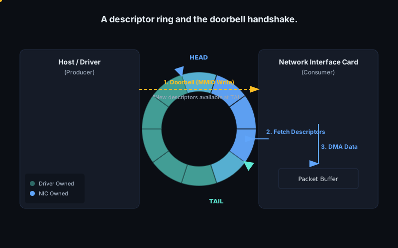
The usual structure is a descriptor ring: a circular array of fixed-size records in DMA-coherent memory. During setup, the driver allocates the ring, obtains its dma_addr_t, and programs device registers with the base address and length. Intel Ethernet devices, for example, expose receive and transmit head and tail registers such as RDH, RDT, TDH, and TDT. The names vary, but the pattern is stable: the ring lives in host memory, and MMIO registers tell the device where it is and which part is valid.
A descriptor is a compact contract. On transmit, it may contain the DMA address of packet data, a byte count, offload flags, and a request for completion status. On receive, it commonly starts as an empty buffer offered by software. After a packet arrives, the device writes status, length, error bits, checksum data, and perhaps an RSS hash. The payload goes to the buffer; the descriptor tells software what happened.
The ring is circular because queues are long-lived. If the ring has N entries, index N - 1 wraps back to 0, avoiding allocation on the fast path. The driver keeps indices such as next_to_use and next_to_clean; the device tracks what it has fetched and completed. Some devices expose that state through MMIO head and tail registers. Others rely on ownership or phase bits inside descriptors, so software can tell who owns an entry without reading a register for every completion.
The central handshake is ownership. Before giving a transmit descriptor to the device, software must finish writing every field the device will read: payload DMA address, length, command bits, and any end-of-packet marker. Only then may it publish the descriptor by advancing a tail register, flipping an ownership bit, changing a phase bit, or some combination. The device performs DMA and later returns ownership by writing completion status or advancing a pointer. Software must not recycle the descriptor or unmap the payload buffer until that completion is visible.
The receive path is the same handshake reversed. Software pre-posts buffers by filling receive descriptors and advancing the receive tail. The NIC owns those entries and may write packets into them. When software later observes a device-written done bit, phase bit, or completion entry, it owns that descriptor again. It can pass the packet upward, replace or reuse the buffer, and repost the descriptor. If RX refill falls behind, the NIC may have link bandwidth available but no host buffers for frames.
The doorbell is the notification register. It is usually an MMIO write into a BAR, often containing the new producer index or queue tail. The useful information is already in shared memory; the register write tells the device to go look. For an Intel-style transmit ring, writing TDT adds descriptors to the ready queue. For NVMe, submission queue tail doorbells announce new commands. This memory queue plus MMIO doorbell shape is everywhere because it amortizes expensive device interaction over batches.
Ordering is what makes the handshake correct. PCIe and the device cannot fetch descriptor fields still sitting in a CPU store buffer, nor can they guess that software intended a descriptor write to happen before a doorbell write. The driver must create that ordering: fill the descriptor, use the appropriate DMA write barrier for coherent descriptor memory, then ring the MMIO doorbell. In Linux, dma_wmb() orders writes to memory shared with a DMA-capable device; MMIO ordering is governed by the I/O accessor rules, so writel() and relaxed variants must be chosen deliberately.
The reverse direction needs matching read-side care. When software sees that the device has returned ownership, it must ensure completion status is observed before consuming the rest of the descriptor or payload metadata. Linux documents dma_rmb() for this purpose: after detecting that the device has released a descriptor, the barrier prevents later CPU reads from being satisfied before the ownership/status read. Without this, a driver can observe a done bit and then read stale length or checksum fields on weaker memory-ordering machines.
Performance comes from batching. A driver may fill many transmit descriptors and ring the doorbell once. A polling loop may clean many receive completions before re-enabling interrupts. Ring size controls outstanding work; too small and the device starves, too large and cache footprint and latency grow. Real NIC drivers treat descriptor rings as per-queue data structures, usually one RX ring and one TX ring per traffic queue, aligned with MSI-X vectors and CPU affinity so the same core tends to touch the same cache lines.
The interview-level invariant is simple but unforgiving: descriptors are the work order, ownership defines who may touch each entry, and the doorbell is only a notification. Correct drivers publish memory before notification and consume completions only after ownership returns.
Sources
5.10 Drivers, kernel and userspace
A driver is the software owner of a device. It turns asynchronous hardware into an interface the rest of the system can use. For a PCIe NIC, that means discovering the function, enabling it, mapping BARs, programming queues, arranging DMA-safe memory, handling interrupts or polling, recovering from reset, and enforcing one owner per function.
In a conventional kernel driver, the device is matched by IDs in PCI configuration space. The driver registers a pci_driver with an ID table, and the kernel calls its probe method when a matching device appears. probe is where ownership begins. The driver enables the PCI function, requests BAR regions, sets a DMA mask, maps MMIO registers, allocates queues and buffers, requests interrupt vectors, and starts the device. The reverse path is remove: stop new work, quiesce the device, disable interrupts, return DMA mappings, unmap BARs, and release ownership.
The CPU does not call device methods in a simple request/return style. Hardware runs concurrently. A transmit path may place descriptors in memory, use a write memory barrier, then ring a doorbell register. A receive path may refill buffers that the NIC will DMA into. An interrupt handler may acknowledge the event and schedule a bottom half or NAPI poll loop to drain completions. Reset handling must assume MMIO state, outstanding DMA, and interrupts can all be in intermediate states. Driver code is mostly about ordering, lifetime, and ownership.
The kernel also protects the rest of the machine from the device. DMA is the central reason. A bus-mastering device can write memory without the CPU executing a store instruction. The DMA API lets the driver express which buffers are visible to the device and in which direction. Coherent allocations suit descriptor rings. Streaming mappings suit packet buffers mapped for one transfer and unmapped when it completes. With an IOMMU, those calls may create I/O virtual address mappings; with non-coherent caches, they may imply cache maintenance. A correct driver does not guess physical addresses.
Many high-performance networking systems move much of the datapath out of the kernel. Kernel crossings, generic socket abstractions, and shared interrupt paths can dominate small-packet cost. Frameworks such as DPDK often want a userspace process to poll completion rings, batch doorbells, manage hugepage-backed packet buffers, and avoid per-packet syscalls. That does not mean userspace can poke arbitrary physical memory or receive raw interrupts without mediation. The kernel still has to establish a safe boundary.
UIO, the Userspace I/O framework, is the thinner mechanism. A small kernel driver binds to the device and exposes memory regions through /dev/uioX; userspace can mmap those regions and access registers or on-device memory directly. Interrupts are represented by reads from the same character device: a blocking read wakes when an interrupt occurs and returns an interrupt count. This is useful for simple devices, prototypes, FPGA control blocks, and hardware whose DMA story is absent or controlled elsewhere. UIO is intentionally small. It does not, by itself, provide the IOMMU-managed DMA isolation expected for assigning a bus-mastering PCIe NIC to an arbitrary process.
VFIO, Virtual Function I/O, is the safer model for direct userspace device access. VFIO exposes a device through file descriptors and ioctls, but keeps the IOMMU in the trust boundary. Devices are organized into IOMMU groups: a group is the smallest set of devices that the platform can isolate from the rest of the system. Userspace can only use a group after it has been detached from host drivers and attached to VFIO, because devices that can reach each other without isolation must be controlled together. The process then creates an IOMMU context, maps its memory into the device's I/O address space, maps BARs, configures interrupts, and drives the hardware directly.
For a NIC, this separation makes userspace drivers viable. The fast path can run in userspace: queue setup, descriptor production and consumption, batching, prefetching, NUMA-aware buffer pools, and busy polling. The privileged path remains mediated: binding the device, checking group isolation, programming the IOMMU, routing MSI-X interrupts, and preventing DMA outside mapped memory. The device sees I/O virtual addresses, not permission to scribble over the host.
There are tradeoffs. A kernel driver integrates naturally with the network stack, traffic control, ethtool, power management, hotplug, and accounting. It can share the NIC through ordinary sockets. A userspace driver usually takes exclusive ownership of a PCI function; host-stack integration must be rebuilt through tap devices, vhost, AF_XDP, or application plumbing. The reward is control: fewer datapath layers and direct responsibility for cache misses, MMIO writes, descriptor formats, and memory ordering.
The interview-level mental model is simple: the driver owns device state transitions and translates between CPU memory rules and device-visible operations. Whether it lives mostly in kernel or userspace, the hard problems remain. Registers have ordering requirements, DMA needs mapped memory with correct lifetimes, interrupts race with teardown, and the device must be stopped before queues and buffers are freed. VFIO and UIO change where the code runs; they do not remove driver discipline.
Sources